Rank: Member
Groups: Member
Joined: 2/1/2012(UTC)
Posts: 332
Location: The Netherlands
Thanks: 4 times
Was thanked: 18 time(s) in 18 post(s)
|
After asking already dozens of questions here and at the DIY audio forums I stumbled across the project gallery.  My B3 still has to arrive, but nevertheless I'm very busy designing it and trying to expand my knowledge about it as much as possible. I will be using the "S/DIF 4 input board", "Sidecar" and the "4 input selection board". This is the design I came up with. 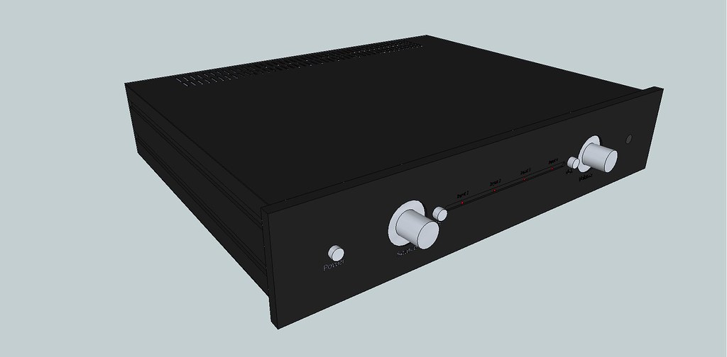 After finding out about the option to use Arduino for controlling the DAC I'm thinking about re-designing it. Because my knowledge about controlling the B3 with Arduino is a bit to limited at the moment I will first build it without. When it is working properly I will try to get Arduino integrated using HiFiDuino based code and an LCD or other type of display. Therefor the front plate needs to be re-designed. For the moment I'm not sure if I will use the same front plate and re-designed it to have a display fitted into it or use a entirely new front plate. It will probably design a new one, because when using Arduino one of the large knobs will become redundant. For those who want to use the sketchup 3D design click here. To be continued... Edited by user Tuesday, April 24, 2012 11:35:37 AM(UTC)
| Reason: Not specified |
|
|
|
|
|
|
Rank: Member
Groups: Member
Joined: 12/7/2011(UTC)
Posts: 474
Location: Amsterdam
Thanks: 31 times
Was thanked: 4 time(s) in 3 post(s)
|
|
|
|
|
|
|
Rank: Member
Groups: Member
Joined: 2/1/2012(UTC)
Posts: 332
Location: The Netherlands
Thanks: 4 times
Was thanked: 18 time(s) in 18 post(s)
|
After I decided that arduino was the way to go, I had to re-design the front plate a bit. In with the LCD display and out with all buttons. The left knob is going to be connected to a rotary power switch and the right knob for controlling all functions. Now I have to think of a nice way of integrating the IR receiver in a way it is not visible. All inscriptions will be engraved. I'm not sure which design I like best.  and  btw. There is a new option to attach files to this post, but it doesn't work yet. It gives the following error message: Access to the path 'D:\inetpub\twistedpearaudio\forum\Uploads' is denied.Edited by user Sunday, April 29, 2012 10:32:45 PM(UTC)
| Reason: Not specified |
|
|
|
|
|
|
Rank: Member
Groups: Member
Joined: 2/1/2012(UTC)
Posts: 332
Location: The Netherlands
Thanks: 4 times
Was thanked: 18 time(s) in 18 post(s)
|
Well it took a while to receive all components. Since last Thursday I've been busy soldering. Yesterday the placids where tuned and today I hooked up the dac, IVY and 4 spdif input board and connected my cd player to it. This was just a test to see if the DAC was working properly. The results: I see a lock light!  So the DAC is working just fine. Tomorrow I'll get a piece of plywood to temporary mount all modules onto it for further testing and try to find the best layout. I'll desolder QN1's heatsink as well and put a larger one in return. It runs a bit to hot imo. When all is up and running I'll proceed with Arduino for controlling the DAC. Here is the evidence of the lock light :-) Edited by user Sunday, May 27, 2012 9:23:07 PM(UTC)
| Reason: typo Corpius attached the following image(s):  IMG_7771_small.jpg (231kb) downloaded 122 time(s). IMG_7770_Small.jpg (211kb) downloaded 211 time(s).You cannot view/download attachments. Try to login or register. |
|
|
|
|
|
|
Rank: Member
Groups: Member
Joined: 1/19/2011(UTC)
Posts: 332
Location: Oslo, Norway
Thanks: 14 times
Was thanked: 17 time(s) in 17 post(s)
|
Lovely jobly :)
Looking forward to hearing your impressions and the continuations of your project :)
|
|
|
|
|
|
Rank: Member
Groups: Member
Joined: 2/1/2012(UTC)
Posts: 332
Location: The Netherlands
Thanks: 4 times
Was thanked: 18 time(s) in 18 post(s)
|
Today I finished a little circuit with a relay. This circuit will be placed between the HDBP and IVY. The relay is switched after the dac has started. This prevents full volume at start-up to my precious power amps when arduino fails to start somehow. The circuit is quite a ugly duck compared to the TPA modules  , not that it matters. I won't be seeing it. It works fine and that's what counts. I'll make a similar circuit, but without the relay to switch the sidecar using arduino. Corpius attached the following image(s): Full volume prevention circuit.jpg (22kb) downloaded 43 time(s). Relay circuit.jpg (229kb) downloaded 71 time(s).You cannot view/download attachments. Try to login or register. |
|
|
|
|
|
|
Rank: Member
Groups: Member
Joined: 1/19/2011(UTC)
Posts: 332
Location: Oslo, Norway
Thanks: 14 times
Was thanked: 17 time(s) in 17 post(s)
|
Nice! 5V from the arduino will switch it on and let the PSU power the IV stage I take it? In that case I can use the same code (with some add-ons) in mine ;) I take it that the delay (from when the Buffalo power on) is done in the arduino code (last part of code after initializing the dac)? Edit: why do you need a circuit to trigger the sidecar? I do this directly from the arduino pin. The Sidecar gets 5V from the arduino (5V out from the regulator) and digital pin 6 trigger it. Edited by user Tuesday, May 29, 2012 4:15:12 PM(UTC)
| Reason: Not specified
|
|
|
|
|
|
Rank: Member
Groups: Member
Joined: 2/1/2012(UTC)
Posts: 332
Location: The Netherlands
Thanks: 4 times
Was thanked: 18 time(s) in 18 post(s)
|
Originally Posted by: gwikse  Nice!
5V from the arduino will switch it on and let the PSU power the IV stage I take it?
In that case I can use the same code (with some add-ons) in mine ;)
I take it that the delay (from when the Buffalo power on) is done in the arduino code (last part of code after initializing the dac)?
Edit: why do you need a circuit to trigger the sidecar? I do this directly from the arduino pin. The Sidecar gets 5V from the arduino (5V out from the regulator) and digital pin 6 trigger it. 5V from one of arduino's digital pins switches the transistor. When this happens 5V from another power supply switches the relay. When the relay is switched the IVY gets powered. This way only a minimal amount of current (< 1mA) is being drawn from the arduino. You can use the exact same code, but you'l need it on a different location when using this for switching the outputs on or off. Best to make a whole new function for this, so it can be switched with the remote. Just like the "show all settings" part. You know what part I mean. Uhmmmm. Now I'm discussing your build on my thread. Lets move this subject to yours.  To answer your question about using such an circuit to trigger the sidecar you must read post #19 to #21 from the "Arduino for controlling the Sabre DAC" thread. Edited by user Tuesday, May 29, 2012 6:19:35 PM(UTC)
| Reason: Not specified |
|
|
|
|
|
|
Rank: Member
Groups: Member
Joined: 2/1/2012(UTC)
Posts: 332
Location: The Netherlands
Thanks: 4 times
Was thanked: 18 time(s) in 18 post(s)
|
Originally Posted by: gwikse I take it that the delay (from when the Buffalo power on) is done in the arduino code (last part of code after initializing the dac)? No, it is not in the code for initializing (starting) the dac, but after that. It is in the setup (void setup) though. After the volume registers are set i'll do a test to be sure the volume is not at its maximum. Only if this test succeeds the relay gets switched. |
|
|
|
|
|
|
Rank: Member
Groups: Member
Joined: 1/19/2011(UTC)
Posts: 332
Location: Oslo, Norway
Thanks: 14 times
Was thanked: 17 time(s) in 17 post(s)
|
5V from arduino to Trigger 1* and pin 6 to Trigger 2* is the way I have connected it and it does not energize the relay from the digital pin 6. When I told you back then that the relay would only require a few mA it was because I was talking about the sidecar circuit and not the required current to energize the relay. I did not tell you this then because I forgot. Triggering the sidecar does not draw a lot of current from an arduino pin. You could use your 5V PSU to power the sidecar Trigger 1* ("VD") and pin6 from arduino to Trigger 2* ("B") * schematic ("PCB print") http://www.twistedpearau...al/sidecar_schematic.pdfEdit: typo Edited by user Tuesday, May 29, 2012 7:12:45 PM(UTC)
| Reason: Not specified
|
|
|
|
|
|
Rank: Member
Groups: Member
Joined: 2/1/2012(UTC)
Posts: 332
Location: The Netherlands
Thanks: 4 times
Was thanked: 18 time(s) in 18 post(s)
|
The Modu slimline chassis arrived. When unpacking t I saw I had coincidentally ordered the wrong size. I wanted to order the 43x35cm, but ordered 43x28cm instead  . This meant I had to do some re-designing. It is now a tighter fit, but still all fits in. It does not leave much room for future expansion of the project. Yesterday I have been drilling and filing holes in the back panel for all inputs and outputs. I still have to do some filing for the RJ45 connector. Yesterday I noticed that I was missing a RCA connector. I thought I had bought all connectors, guess not. I made a panel with lots of venting holes that slides into the chassis on a rail. All modules, except for the arduino and lcd, are going to be mounted onto this panel. This way I can easily slide it all in or out for easy working on it. I will add some extra venting holes to the original bottom panel. Edited by user Saturday, June 9, 2012 4:28:02 PM(UTC)
| Reason: Not specified Corpius attached the following image(s): IMG_7819.JPG (242kb) downloaded 282 time(s). IMG_7820.JPG (216kb) downloaded 230 time(s). IMG_7825.JPG (222kb) downloaded 185 time(s). IMG_7826.JPG (220kb) downloaded 134 time(s).You cannot view/download attachments. Try to login or register. |
|
|
|
|
|
|
Rank: Member
Groups: Member
Joined: 2/1/2012(UTC)
Posts: 332
Location: The Netherlands
Thanks: 4 times
Was thanked: 18 time(s) in 18 post(s)
|
After neglecting this thread at the project gallery it was about time that I posted some more about my progress. I can report that the build is more or less finished, meaning that everything is working and it sits proud next to my other audio gear. There are some future plans to improve some parts, but that's why it is a diy project. It's never ready I wrote a large article about the DAC on my website and to post it also here would take me to much time, so here is the link: My BIII build |
|
|
|
|
|
|
Rank: Member
Groups: Member
Joined: 1/6/2012(UTC)
Posts: 305
Location: Plainfield, IL
Thanks: 11 times
Was thanked: 26 time(s) in 21 post(s)
|
Most impressive! Excellent work on the site and the DAC! I like what you did with the code, particularly that minimal display. Highest marks!!!!! |
|
|
|
|
|
|
Rank: Member
Groups: Member
Joined: 3/24/2012(UTC)
Posts: 10
Location: UK
|
Hi Corpus A great build write up on your web site. A Really interesting read. Thanks 
|
|
|
|
|
|
Rank: Administration
Groups: Administration, Customer
Joined: 10/24/2006(UTC)
Posts: 3,979
Location: Nashville, TN
Thanks: 25 times
Was thanked: 89 time(s) in 83 post(s)
|
Been super busy past couple weeks, but just wanted to pop in and say super DIY work!!! Love it!
|
|
|
|
|
|
Rank: Member
Groups: Member
Joined: 2/1/2012(UTC)
Posts: 332
Location: The Netherlands
Thanks: 4 times
Was thanked: 18 time(s) in 18 post(s)
|
Originally Posted by: SCompRacer Most impressive! Excellent work on the site and the DAC! I like what you did with the code, particularly that minimal display. Highest marks!!!!! Originally Posted by: jshaun Hi Corpus A great build write up on your web site. A Really interesting read. Thanks Originally Posted by: Russ White Been super busy past couple weeks, but just wanted to pop in and say super DIY work!!! Love it! Thanks! This was my first real diy project, but thanks to it I really got infected with the diy virus! There is definitely more to come! |
|
|
|
|
|
|
Rank: Member
Groups: Member
Joined: 1/19/2011(UTC)
Posts: 332
Location: Oslo, Norway
Thanks: 14 times
Was thanked: 17 time(s) in 17 post(s)
|
Very nice build and write up :)
|
|
|
|
|
|
Rank: Member
Groups: Member
Joined: 12/7/2011(UTC)
Posts: 474
Location: Amsterdam
Thanks: 31 times
Was thanked: 4 time(s) in 3 post(s)
|
Hi Corprius,
Good to hear you're booked results as this!
Do you also have an overview picture of the inside to get a good picture of the hookup?
Rgds,
Jordo
|
|
|
|
|
|
Rank: Member
Groups: Member
Joined: 2/1/2012(UTC)
Posts: 332
Location: The Netherlands
Thanks: 4 times
Was thanked: 18 time(s) in 18 post(s)
|
Yes, that`s missing in my article! I must have it somewhere. I`ll post when i find it. |
|
|
|
|
|
|
Rank: Member
Groups: Member
Joined: 12/7/2011(UTC)
Posts: 474
Location: Amsterdam
Thanks: 31 times
Was thanked: 4 time(s) in 3 post(s)
|
Originally Posted by: Corpius Yes, that`s missing in my article! I must have it somewhere. I`ll post when i find it. Great! I'm curious :D
|
|
|
|
|
|
Forum Jump
You cannot post new topics in this forum.
You cannot reply to topics in this forum.
You cannot delete your posts in this forum.
You cannot edit your posts in this forum.
You cannot create polls in this forum.
You cannot vote in polls in this forum.

