Rank: Member
Groups: Member
Joined: 10/28/2016(UTC) Posts: 32  Location: England Thanks: 7 times
Was thanked: 3 time(s) in 3 post(s)
|
Completed my DAC / Network streamer and it sounds fantastic!
Components from TPA include:
Buffalo III ES9018 DAC
IVY-III I/V Stage
Placid HD
Placid HD Bipolar
OTTO-II 2:1 Mux
Amanero USB module
Others/Specs
AMB Sigma11 PCB to provide high current power to Arduino and RPi
Raspberry Pi3 with RuneAudio
Kali Reclocker (RPi isolation and reclocking)
Arduino Due (controls power on/off, inputs, volume, DAC options, remote control, etc.)
Custom Universal Signal Isolator shield for the Due (www.dimdim.gr)
Arduino code for TFT display by dimdim (thank you for all his help also), based on the hifiduino code, display design and menus further customised by myself.
TFT display
5v relay (controlled by Arduino turn power supply on/off to Placid HD and Placid HD BP)
2x9V Toroidal Transformer - Placid HD
2x15V Toroidal Transformer - Placid HD BP
2x25V Toroidal Transformer - AMB Sigma11
HiFi2000 case with custom front and rear panels
Inputs - S/PDIF (Coaxial, BNC, Toslink, AES/EBU), USB
RPi Inputs - 2x USB, 1x Ethernet, 1x USB for WiFi Dongle
This was my first real DIY audio project having only started having a go making cables a few months prior. An interest all started when I got a Raspberry Pi and started looking at the possibilities. It was a project which I thoroughly enjoyed and now complete, I miss doing it. Looking at what the next one could be... As you can see from the internal pictures of the build I didn't make it easy for myself, and it is very compact, making the design, planning and coordination quite complex! If I was to do it again I would definitely splash out on the next largest enclosure. However, being the first project I feel I have learned so much (although really just basic skills of soldering, wiring and assembly).
A huge thanks to Twisted Pear Audio, Russ White and Brian Donegan, as well as the other guys on the forum who have helped troubleshoot a number of issues throughout the build, who's advice was invaluable! The B3 Integration Guide by Leon van Bommel was a massive help, thanks to him also who answered my queries on the forum!
Thoroughly pleased with the DAC, for which I truly believe competes with any commercial product I have heard.
[img=https://flic.kr/p/26JYy5A]DAC Front[/img]
[img=https://flic.kr/p/25rkaz2]Front Detail - Volume Knob[/img]
[img]https://flic.kr/p/25rkaXX[/img]
[img=https://flic.kr/p/25rkaXX]Front Detail - Logo[/img]
[img=https://flic.kr/p/JF9oFU]Front with remote and TFT screen on[/img]
[img=https://flic.kr/p/25HnS9N]Rear panel with custom cables[/img]
[img=https://flic.kr/p/JF9oLy]Rear panel[/img]
[img=https://flic.kr/p/JF9pJq]Internal 1[/img]
[img=https://flic.kr/p/25HnT7j]Internal 2[/img]
[img=https://flic.kr/p/JF9p5Q]Internal 3[/img]
[img=https://flic.kr/p/JF9oij]TFT 'Welcome Screen'[/img]
[img=https://flic.kr/p/JF9ojm]TFT Logo / Signature startup screen[/img]
[img=https://flic.kr/p/25HnRsC]TFT 'Home Screen'[/img]
[img=https://flic.kr/p/JF9ofJ]Screen - Input/Settings Menu[/img]
|
 1 user thanked tdmckellar for this useful post.
|
|
|
|
Rank: Member
Groups: Member
Joined: 10/28/2016(UTC) Posts: 32 Location: England Thanks: 7 times
Was thanked: 3 time(s) in 3 post(s)
|
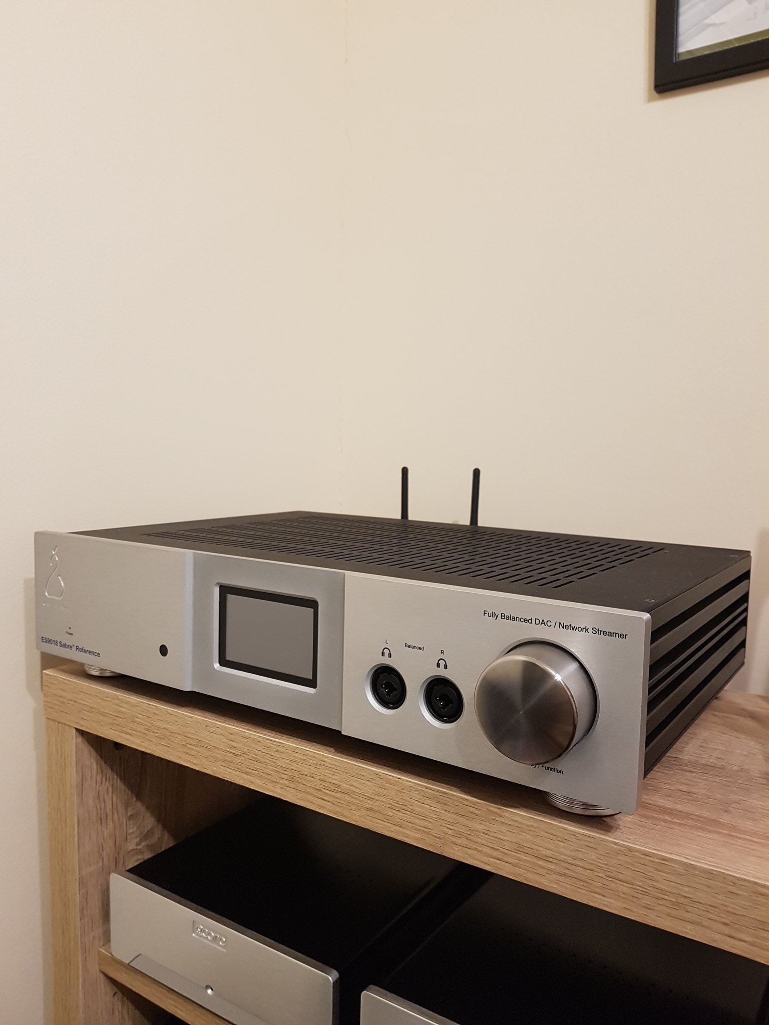 Front 2 Front 2 by David McKellar, on Flickr 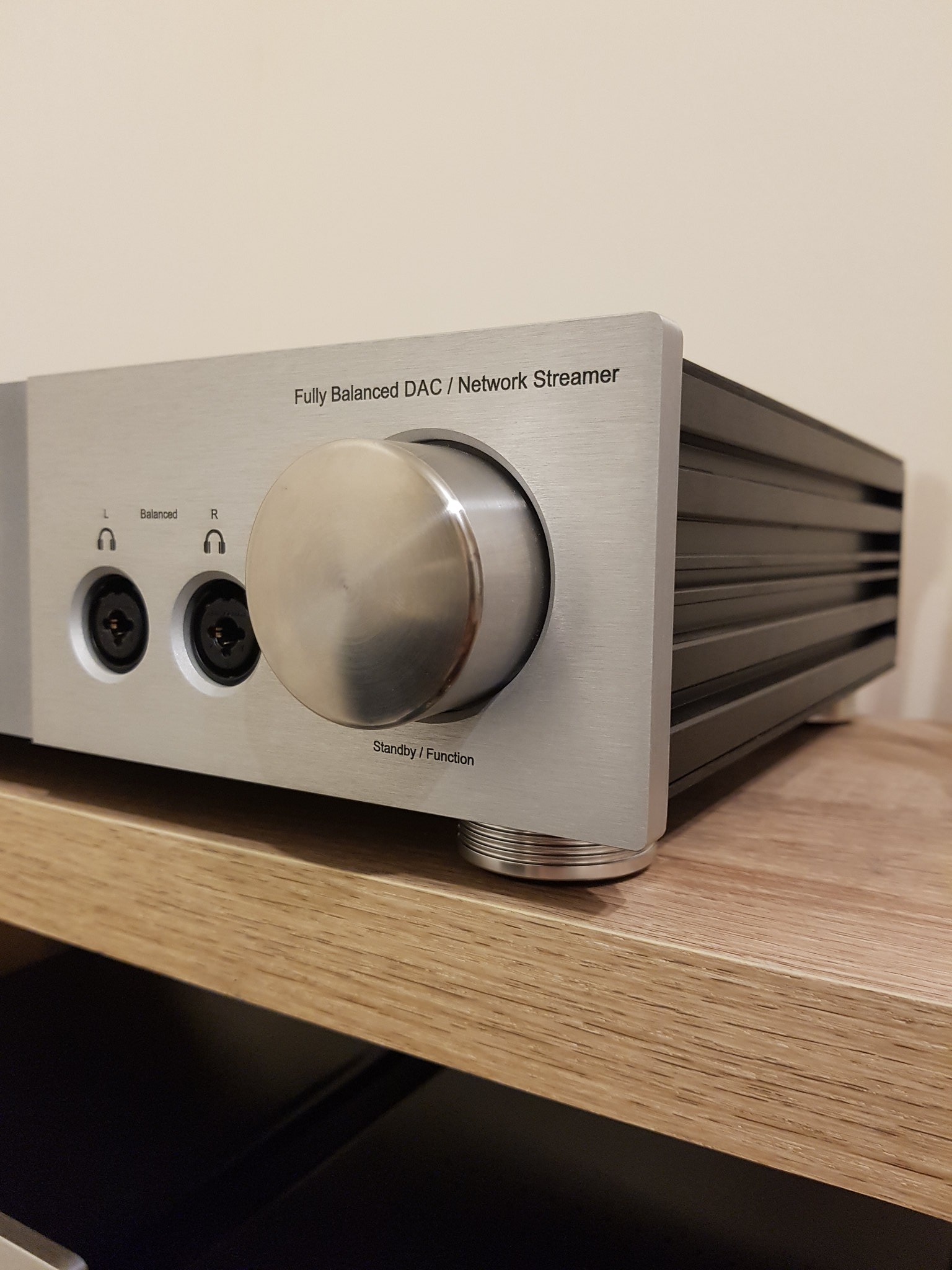 Front Detail - Volume knob and text Front Detail - Volume knob and text by David McKellar, on Flickr 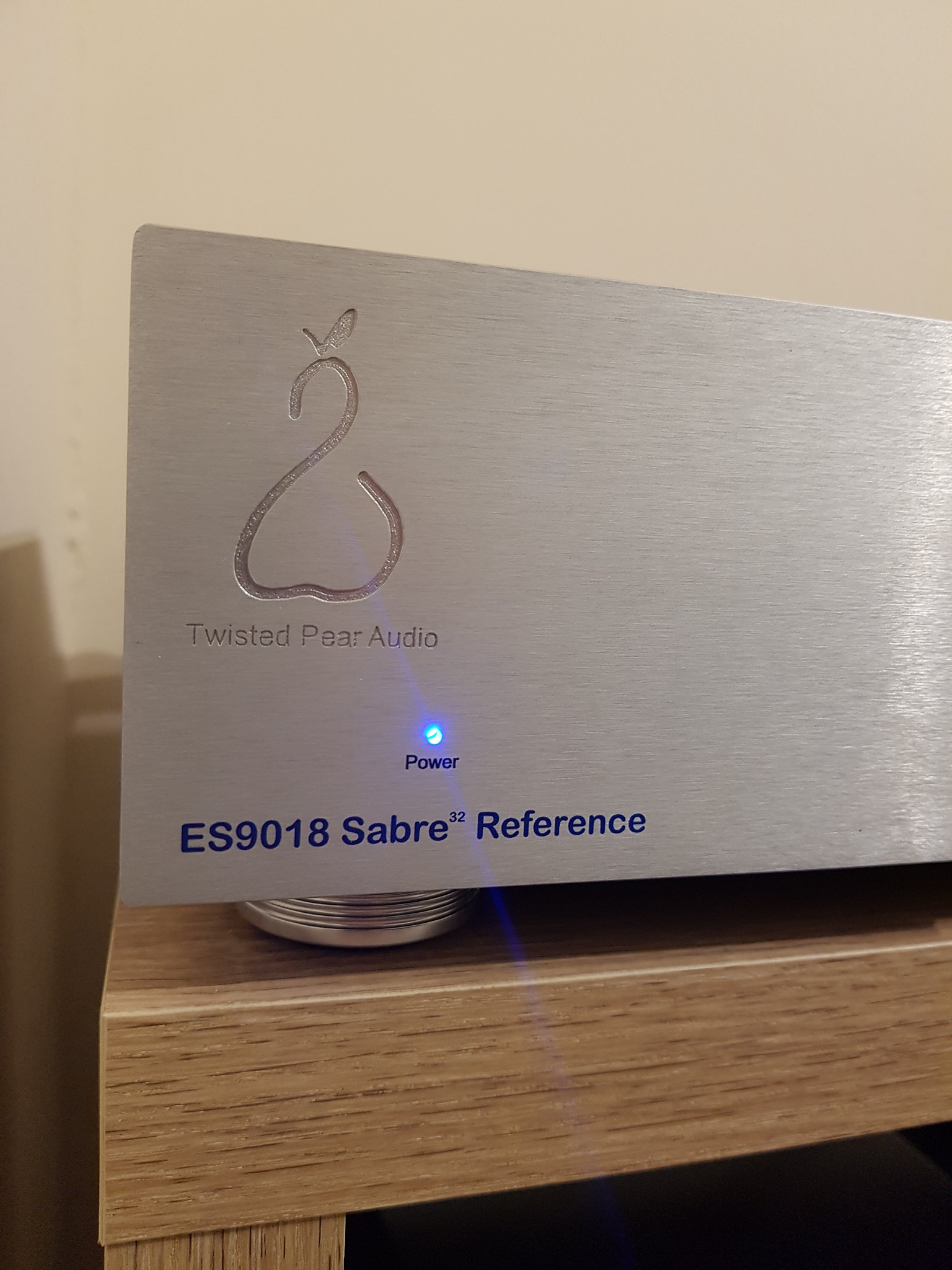 Front Detail - TPA logo and light Front Detail - TPA logo and light by David McKellar, on Flickr 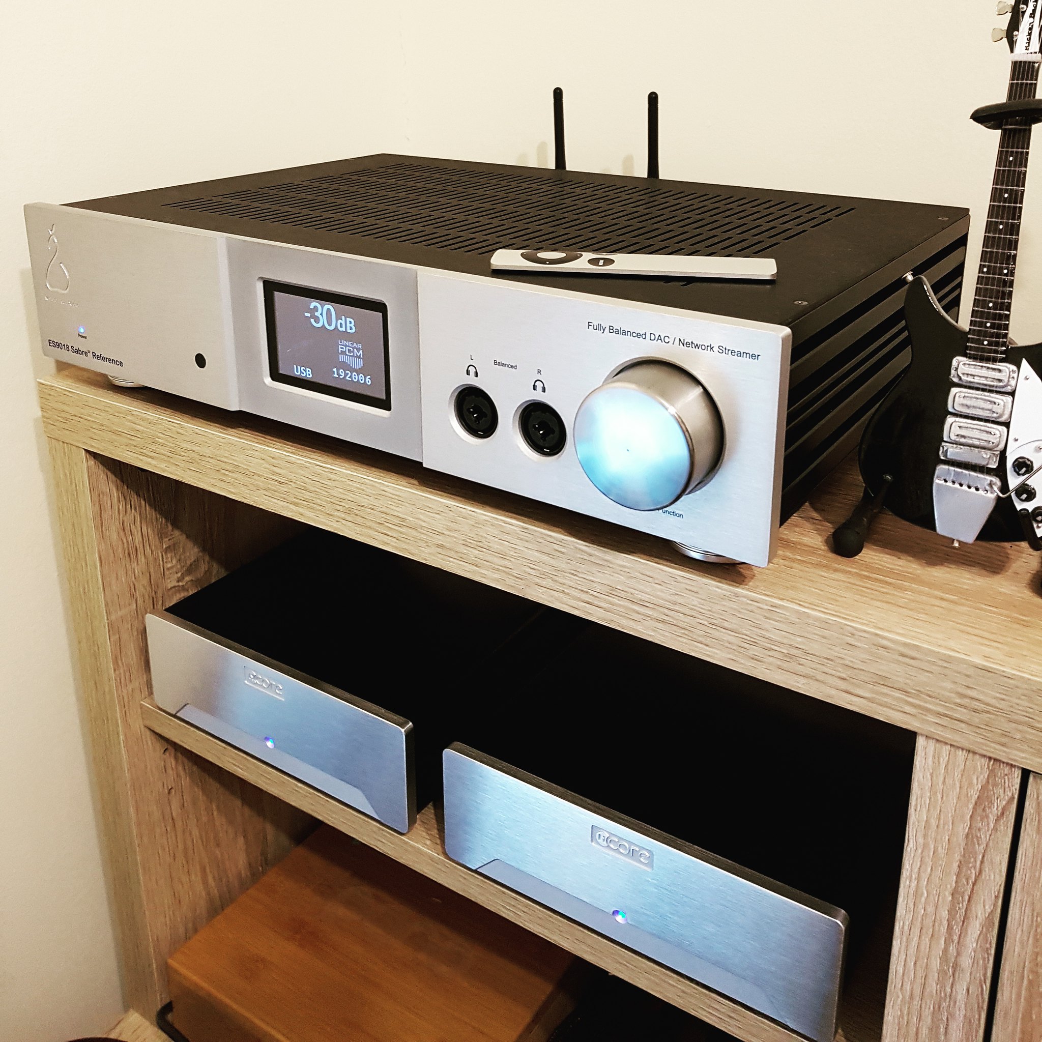 Front 1 Front 1 by David McKellar, on Flickr 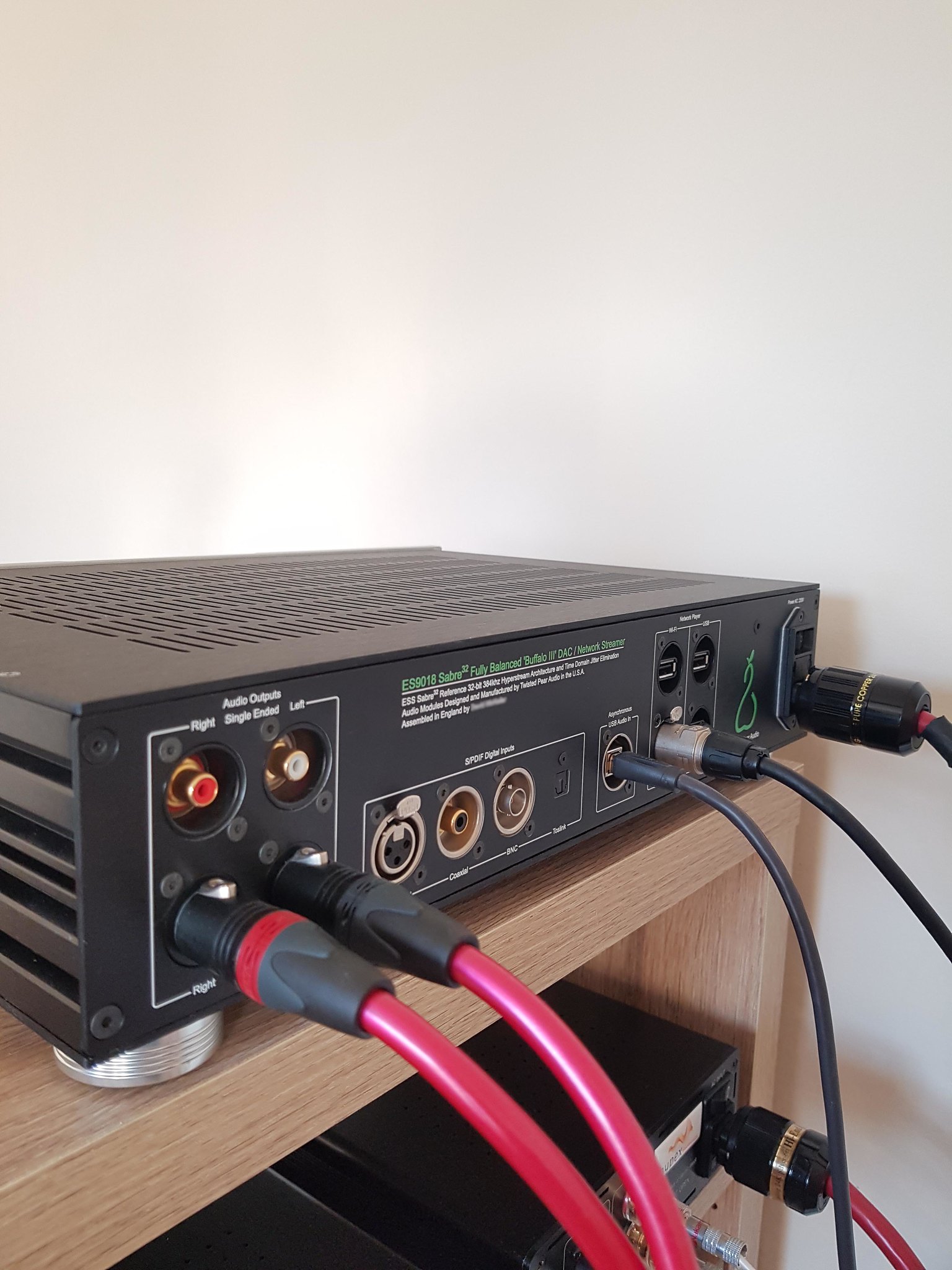 Rear 1 Rear 1 by David McKellar, on Flickr 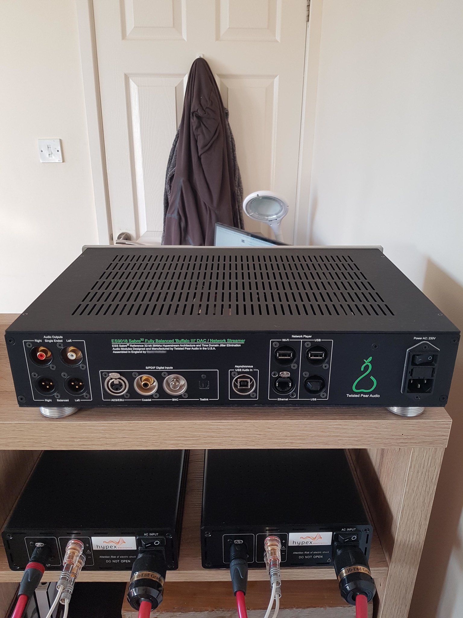 Rear 2 Rear 2 by David McKellar, on Flickr 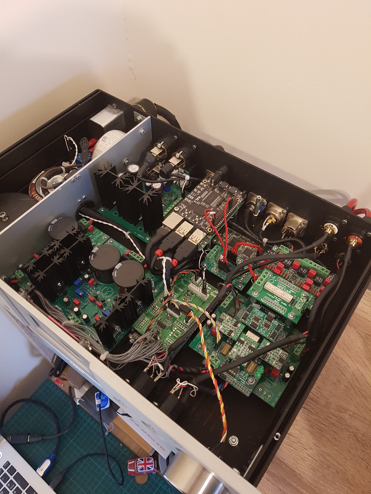 Internal 1 Internal 1 by David McKellar, on Flickr 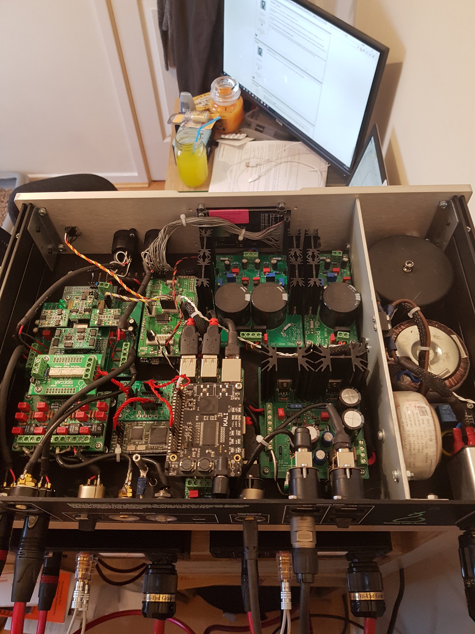 Internal 2 Internal 2 by David McKellar, on Flickr 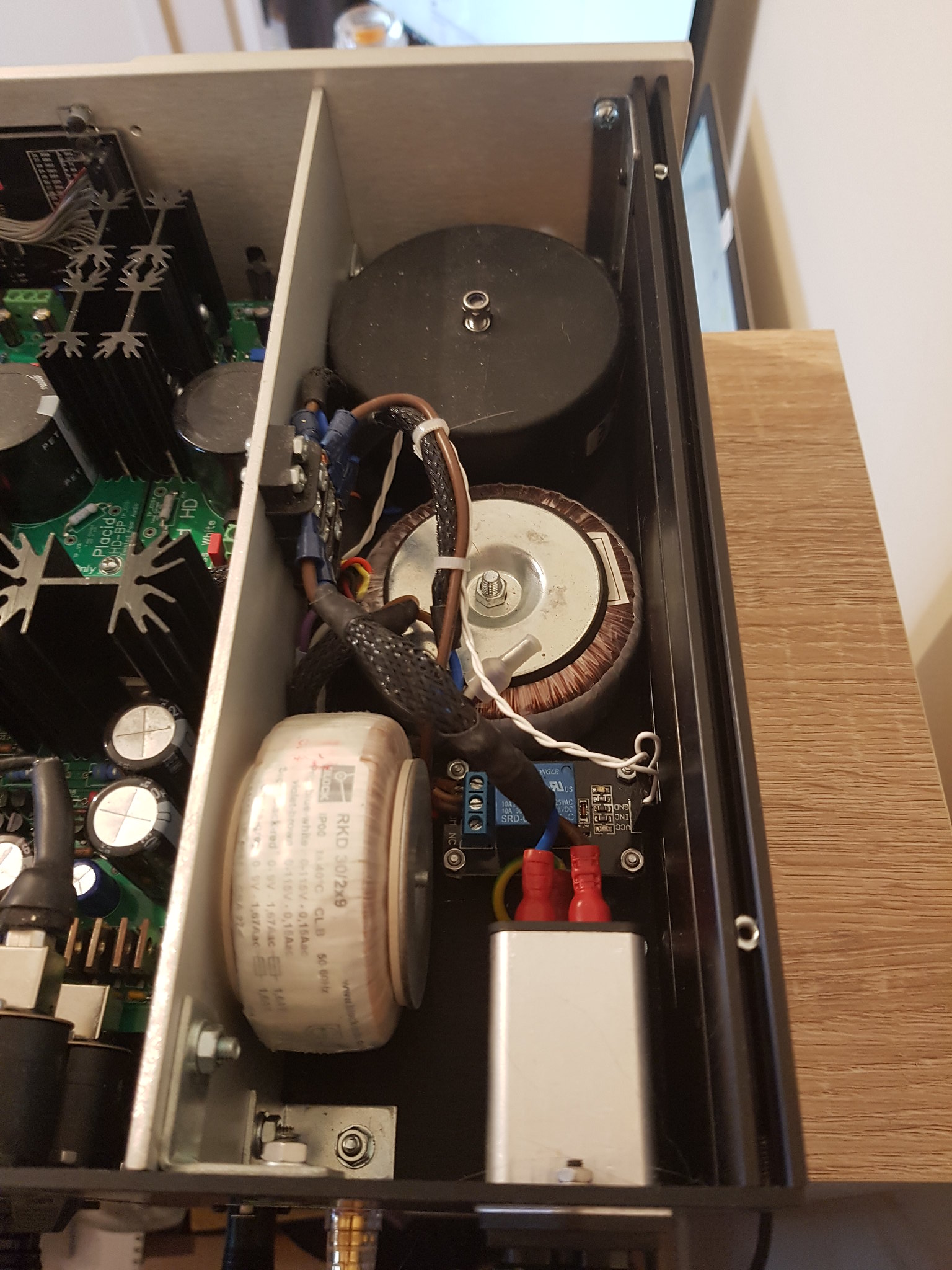 Internal 3 Internal 3 by David McKellar, on Flickr 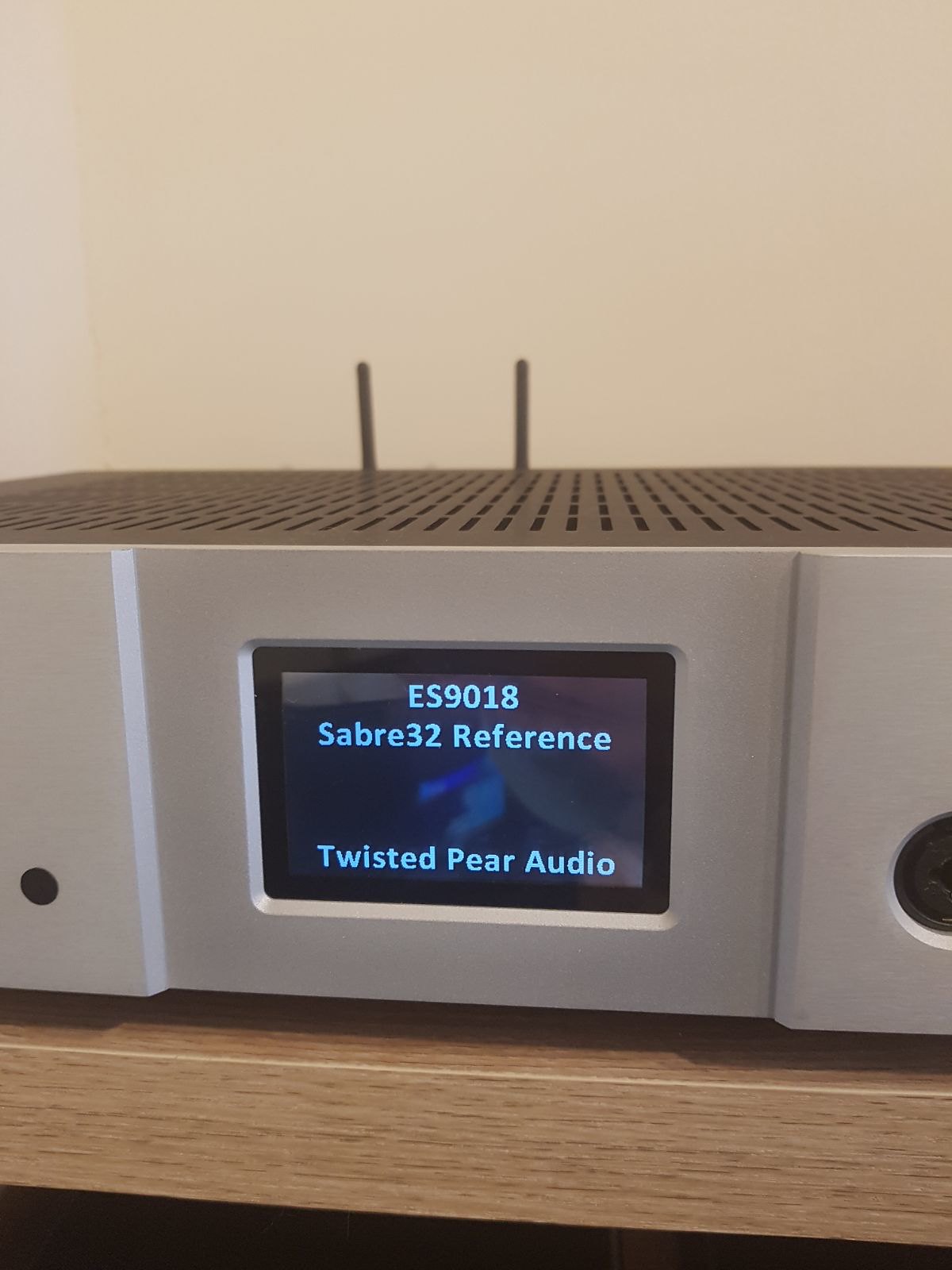 Screen - Power on welcome Screen - Power on welcome by David McKellar, on Flickr 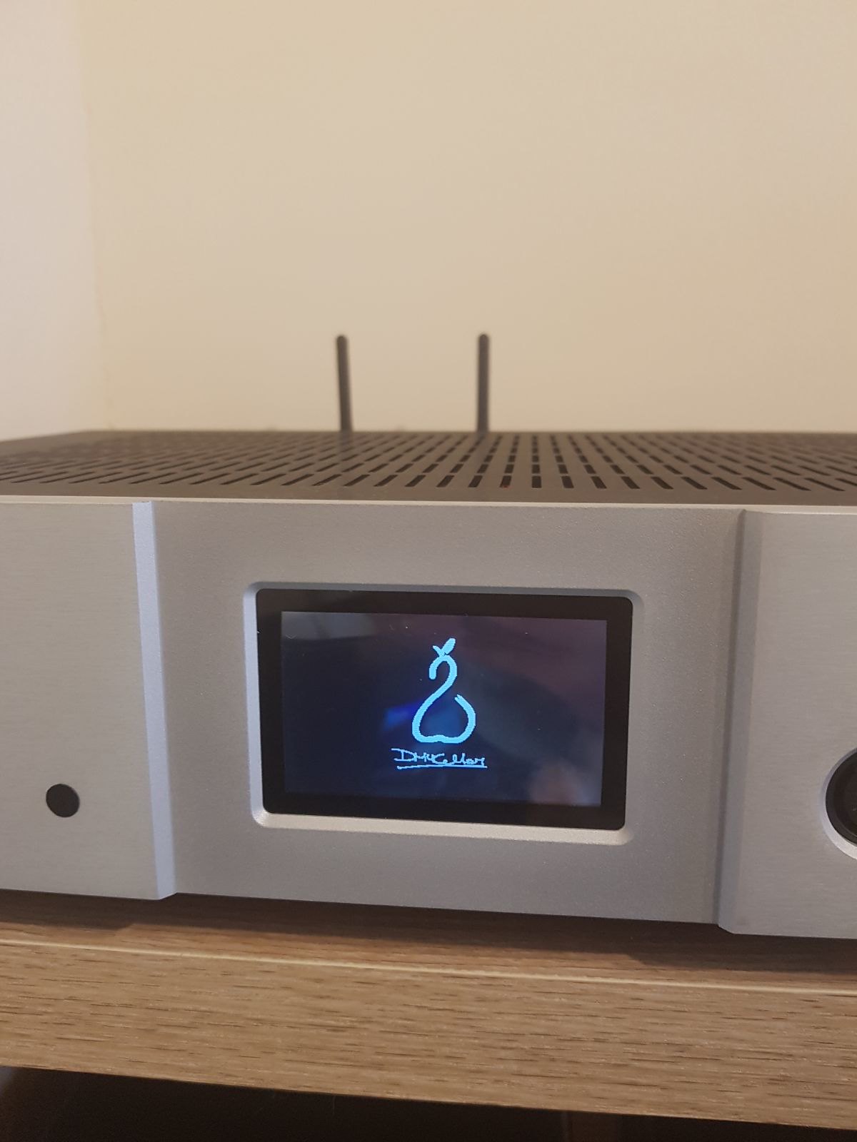 Screen - Power on logo Screen - Power on logo by David McKellar, on Flickr 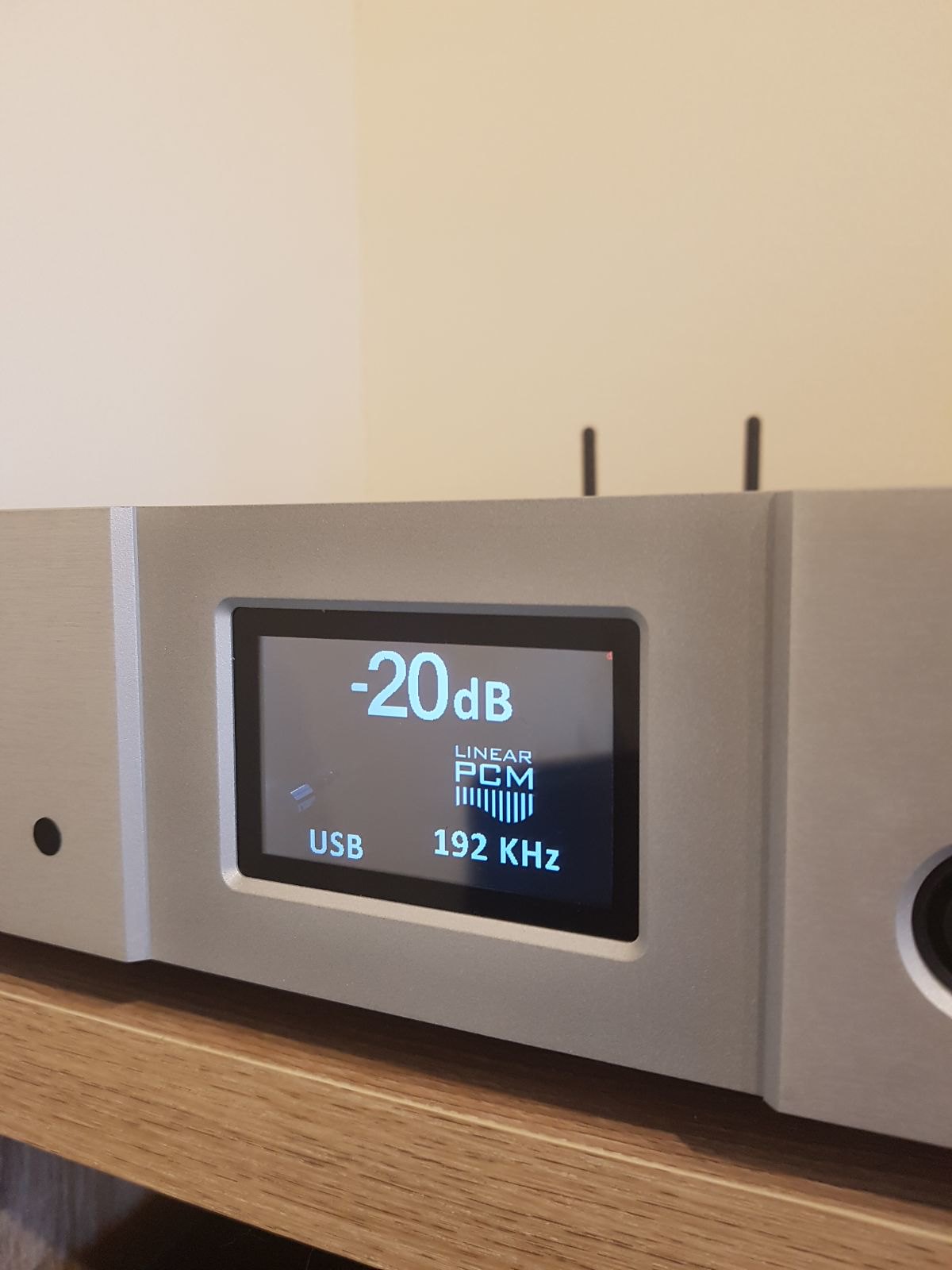 Screen - Default Home Screen - Default Home by David McKellar, on Flickr 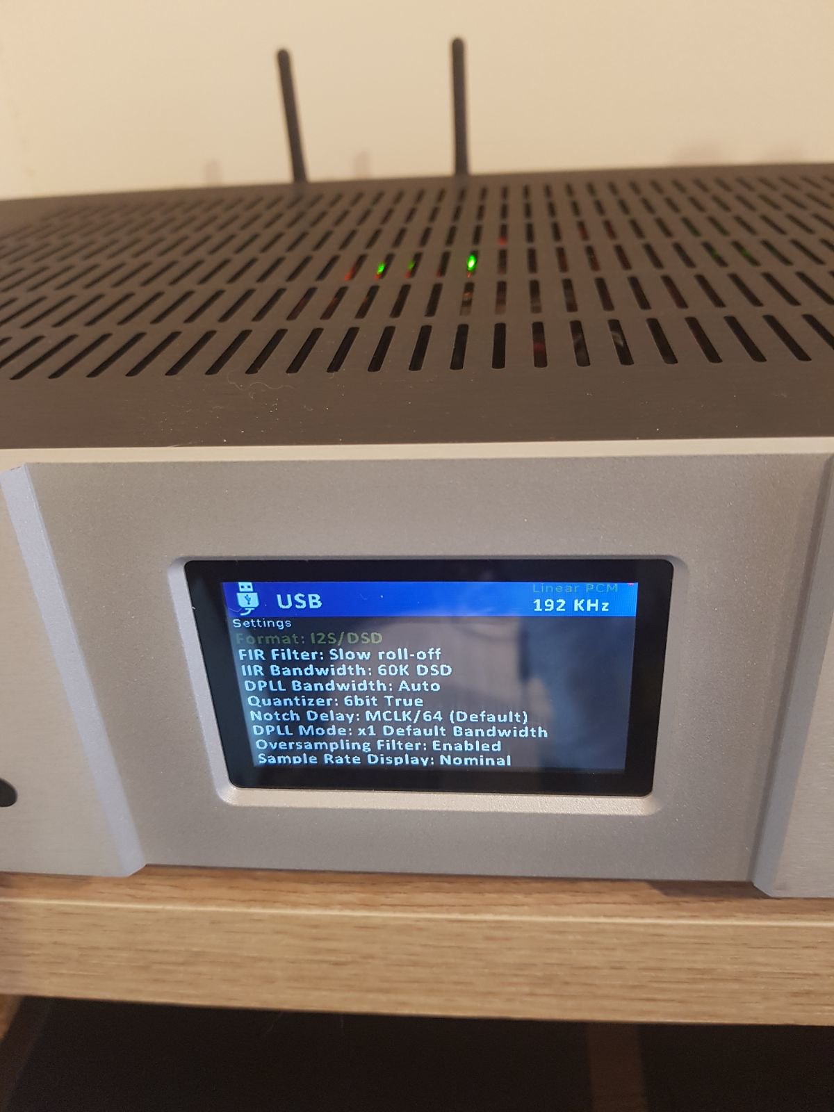 Screen - USB Screen - USB by David McKellar, on Flickr
|
|
|
|
|
|
Rank: Advanced Member
Groups: Member
Joined: 12/28/2008(UTC)
Posts: 48
Location: Pax River MD
|
Beautiful!!! Can you elaborate more on how you did the display?
|
|
|
|
|
|
Rank: Member
Groups: Member
Joined: 10/28/2016(UTC) Posts: 32 Location: England Thanks: 7 times
Was thanked: 3 time(s) in 3 post(s)
|
|
1 user thanked tdmckellar for this useful post.
|
|
|
|
Rank: Member
Groups: Member
Joined: 8/5/2012(UTC) Posts: 208  Thanks: 4 times
Was thanked: 16 time(s) in 14 post(s)
|
You might have to pay Russ and Brian royalties for using the TP logo on the LCD :-)
|
|
|
|
|
|
Rank: Member
Groups: Member
Joined: 10/28/2016(UTC) Posts: 32 Location: England Thanks: 7 times
Was thanked: 3 time(s) in 3 post(s)
|
I might have to also pay for it being plastered all over the front and back panels as well!... haha
|
|
|
|
|
|
Rank: Administration
Groups: Administration, Customer
Joined: 10/24/2006(UTC)
Posts: 2,869
Location: Massachusetts, USA
Thanks: 2 times
Was thanked: 141 time(s) in 134 post(s)
|
|
|
|
|
|
|
Rank: Member
Groups: Member
Joined: 5/17/2013(UTC) Posts: 4  Thanks: 5 times
|
Originally Posted by: tdmckellar  Completed my DAC / Network streamer and it sounds fantastic!
Custom Universal Signal Isolator shield for the Due (www.dimdim.gr)
Well done!  I got inspired to improve my BIII... Could you tell me where to buy the Universal Isolator? I found out that there is no link on dimdim1s page to buy it... Thanks and regards 
|
|
|
|
|
|
Rank: Member
Groups: Member
Joined: 8/5/2012(UTC) Posts: 208 Thanks: 4 times
Was thanked: 16 time(s) in 14 post(s)
|
If you contact DimDim via his page I'm sure he can help you out there.
If you get stuck I have DipTrace files for I2C isolator and reset pin optocoupler isolator circuits (you need both circuits to isolate the ES9028/38) that you can use to get boards made.
Another option is to use the TPA Hermes-BBB board. It has I2C and I2S isolators (no reset pin isolator tho, but a simple relay will also do the job, and not needed by the ES9018 in any case)
BTW: DimDim's board includes a flash ROM so you can remember settings such as selected input
|
1 user thanked Possum for this useful post.
|
|
|
|
Rank: Member
Groups: Member
Joined: 4/5/2019(UTC) Posts: 1 Location: PR
|
Originally Posted by: Possum If you contact DimDim via his page I'm sure he can help you out there.
If you get stuck I have DipTrace files for I2C isolator and reset pin optocoupler isolator circuits (you need both circuits to isolate the ES9028/38) that you can use to get boards made.
Another option is to use the TPA Hermes-BBB board. It has I2C and I2S isolators (no reset pin isolator tho, but a simple relay will also do the job, and not needed by the ES9018 in any case)
BTW: DimDim's board includes a flash ROM so you can remember settings such as selected input
Thanks for the advise... I just tried to contact him... One reason I'd like to use dimdim solution is that I already have most parts (arduino, tft module) and to take advantage of the flash use...  Best regards |
Adriano |
|
|
|
|
|
Rank: Member
Groups: Member
Joined: 8/5/2012(UTC) Posts: 208 Thanks: 4 times
Was thanked: 16 time(s) in 14 post(s)
|
His page allows you to download the PCB design. You can always send it off to someone like PCBWay to get made
|
1 user thanked Possum for this useful post.
|
|
|
|
Rank: Member
Groups: Member
Joined: 10/28/2016(UTC) Posts: 32 Location: England Thanks: 7 times
Was thanked: 3 time(s) in 3 post(s)
|
Yes that's just what I did, downloaded the PCB design then used a website to upload the file and get a number of copies printed. I can't remember which site I used, but it was a fairly reasonable price and didn't have any problems (i've also never done anything like this before!). DimDim also includes a Bill of Materials with Part numbers which are really useful, you can use this to find each bit you need from sites like Mouser, CPC and Farnell.
|
1 user thanked tdmckellar for this useful post.
|
|
|
|
Rank: Member
Groups: Member
Joined: 5/17/2013(UTC) Posts: 4 Thanks: 5 times
|
Yep, I'll follow this way...
Thanks!!!
|
|
|
|
|
|
Forum Jump
You cannot post new topics in this forum.
You cannot reply to topics in this forum.
You cannot delete your posts in this forum.
You cannot edit your posts in this forum.
You cannot create polls in this forum.
You cannot vote in polls in this forum.

