Rank: Member
Groups: Member
Joined: 6/17/2008(UTC) Posts: 921  Thanks: 1 times
Was thanked: 70 time(s) in 69 post(s)
|
If we are dealing with a bad via, try reheating this spot.  cut170116-4.jpg (16kb) downloaded 23 time(s).And while you have the PCB pulled from the enclosure, take a good sharp (not to much flash) picture of the bottom side and post it.
|
|
|
|
|
|
Rank: Member
Groups: Member
Joined: 11/16/2015(UTC) Posts: 21  Location: İstanbul
|
Originally Posted by: avr300  If you do have -2,49 at C8, Quote:
C8B - ... -2.49
IC2 3 ... - 0.99
then you also need to have -2,49 at the pad where pin3 is supposed to make contact - it only one single track on the PCB. cut170116-3.jpg (25kb) downloaded 21 time(s).Get hold of your magnifying glass ;-) We need to get this running so you can listen. Now I recognized in between c8 - leg and opamp 3 leg something is hapening. I just made measurement 4 in a row 1 min in between I always read -2.49 at R13B leg no 1 BUT what I read at C8 - leg and opamp leg 3 changes. 3 times of this try I read at c8 - 0.99 Opamp leg 3 each time different voltage is not stabil. And it dont fix at a figure flactuating while I touch. ???
|
|
|
|
|
|
Rank: Member
Groups: Member
Joined: 6/17/2008(UTC) Posts: 921 Thanks: 1 times
Was thanked: 70 time(s) in 69 post(s)
|
Then you have to pull the board and have a look underneath to see what's going on in this area. cut170116-5.jpg (16kb) downloaded 26 time(s).Edited by user Sunday, January 17, 2016 3:04:56 PM(UTC)
| Reason: Not specified
|
|
|
|
|
|
Rank: Member
Groups: Member
Joined: 6/17/2008(UTC) Posts: 921 Thanks: 1 times
Was thanked: 70 time(s) in 69 post(s)
|
When the board is working, no matter what this areas has to be same potential. cut170116-6.jpg (26kb) downloaded 37 time(s).
|
|
|
|
|
|
Rank: Member
Groups: Member
Joined: 11/16/2015(UTC) Posts: 21 Location: İstanbul
|
Originally Posted by: avr300 If we are dealing with a bad via, try reheating this spot. cut170116-4.jpg (16kb) downloaded 23 time(s).And while you have the PCB pulled from the enclosure, take a good sharp (not to much flash) picture of the bottom side and post it. 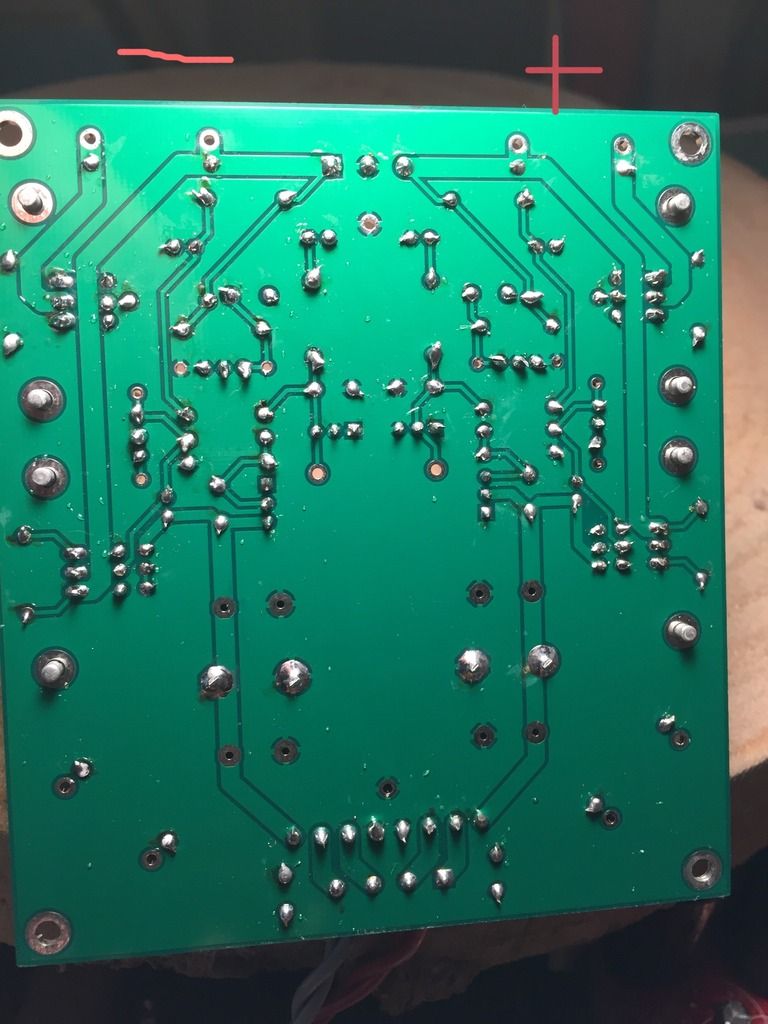
|
|
|
|
|
|
Rank: Member
Groups: Member
Joined: 6/17/2008(UTC) Posts: 921 Thanks: 1 times
Was thanked: 70 time(s) in 69 post(s)
|
This is the interesting part. cut170116-8.jpg (31kb) downloaded 44 time(s).
|
|
|
|
|
|
Rank: Member
Groups: Member
Joined: 11/16/2015(UTC) Posts: 21 Location: İstanbul
|
Originally Posted by: avr300 When the board is working, no matter what this areas has to be same potential. cut170116-6.jpg (26kb) downloaded 37 time(s). Here I took some pictures First at negative leg of cap Second at resistor 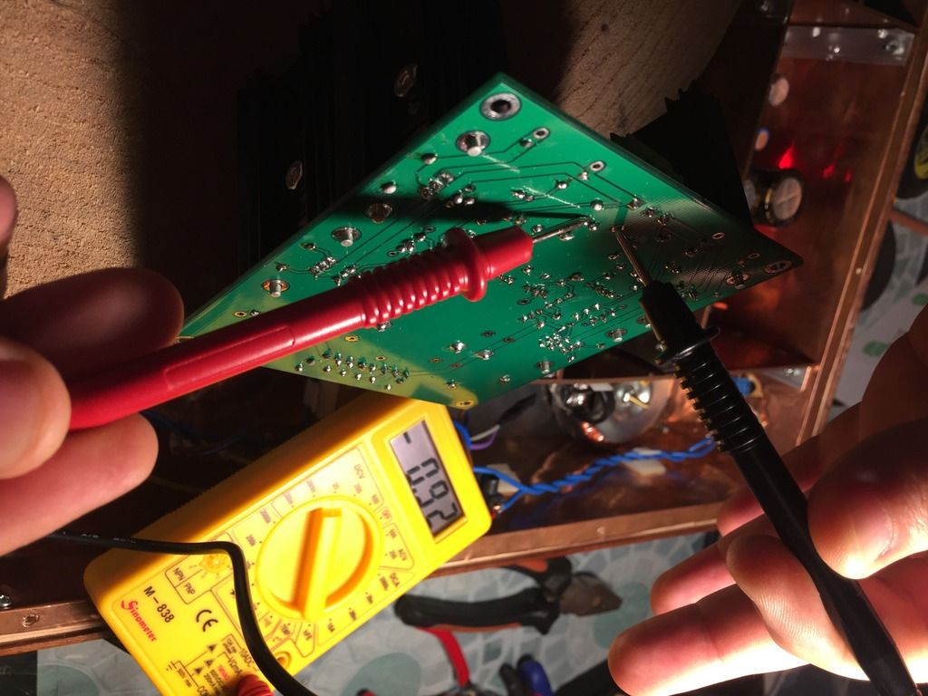 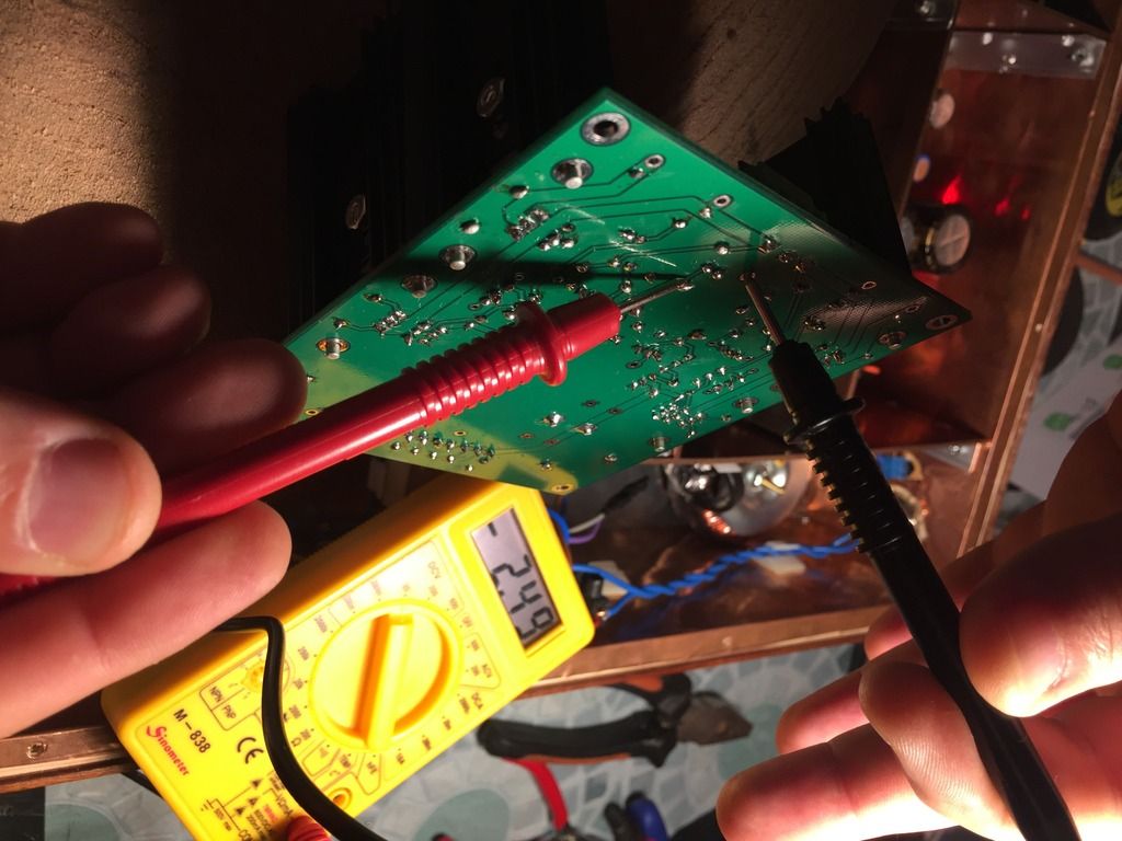 Here the tripod for mobile phone or how you call it :) :) :) 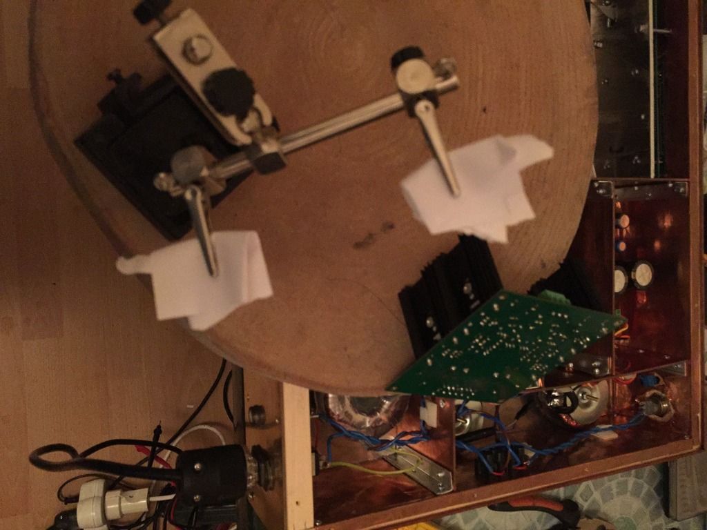
|
|
|
|
|
|
Rank: Member
Groups: Member
Joined: 11/16/2015(UTC) Posts: 21 Location: İstanbul
|
Originally Posted by: avr300 This is the interesting part. cut170116-8.jpg (31kb) downloaded 44 time(s). I renewed all solders here. But still the same.
|
|
|
|
|
|
Rank: Member
Groups: Member
Joined: 6/17/2008(UTC) Posts: 921 Thanks: 1 times
Was thanked: 70 time(s) in 69 post(s)
|
Place a piece of wire (cut some off a resistor leg) between the two solder points.
|
|
|
|
|
|
Rank: Member
Groups: Member
Joined: 11/16/2015(UTC) Posts: 21 Location: İstanbul
|
Originally Posted by: avr300 Place a piece of wire (cut some off a resistor leg) between the two solder points. And the oscar goes to avr300 Thanks a lot. I read now - 2.22 at both points resistor leg and cap - leg and also opamp 3 rd pin. But it now reaches 14.70 v and fixes. No flactuation at all. I could not imagine that there could be a problem with pcb. Again thank you.
|
|
|
|
|
|
Rank: Member
Groups: Member
Joined: 11/16/2015(UTC) Posts: 21 Location: İstanbul
|
May I ask one last question.
What shall be the ideal shunted current.
|
|
|
|
|
|
Rank: Member
Groups: Member
Joined: 6/17/2008(UTC) Posts: 921 Thanks: 1 times
Was thanked: 70 time(s) in 69 post(s)
|
50 to 100mA depends on your ability to cool the thing.
Congrats. I'm glad to have helped you.
|
|
|
|
|
|
Rank: Member
Groups: Member
Joined: 6/17/2008(UTC) Posts: 921 Thanks: 1 times
Was thanked: 70 time(s) in 69 post(s)
|
Originally Posted by: tiguan May I ask one last question.
What shall be the ideal shunted current. Feel free to ask all the questions you want.
|
|
|
|
|
|
Forum Jump
You cannot post new topics in this forum.
You cannot reply to topics in this forum.
You cannot delete your posts in this forum.
You cannot edit your posts in this forum.
You cannot create polls in this forum.
You cannot vote in polls in this forum.

