Rank: Member
Groups: Member
Joined: 11/16/2015(UTC) Posts: 21  Location: İstanbul
|
Yesterday I finished my build for the Placid HD bipolar kit. Positive rail works without problem after powering in 2 sec reaches to +15 v But negative rail starts with -11 or -12 and very very slow reaches -15 v meanwhile dacboard locks itself What shall be the reason ?? Bad solder or should I look something else Additionally even for both rail CCS currents are the same , shunted currents are not the same 65 mA for positive rail 54 mA for negative rail Thanks in advance for assistance Edited by user Sunday, January 17, 2016 7:52:58 PM(UTC)
| Reason: Not specified
|
|
|
|
|
|
Rank: Member
Groups: Member
Joined: 11/16/2015(UTC) Posts: 21 Location: İstanbul
|
One more thing...
For example I power the DAC, wait little bit when it is -14 v adjust with the related VR to -15 but it do not stop increasing still -15.01; -15.02 ; -15.03 ....it increases.
|
|
|
|
|
|
Rank: Member
Groups: Member
Joined: 11/16/2015(UTC) Posts: 21 Location: İstanbul
|
I checked all solder. No cold joint.
Shall it be a faulty VR
|
|
|
|
|
|
Rank: Member
Groups: Member
Joined: 6/17/2008(UTC) Posts: 921  Thanks: 1 times
Was thanked: 70 time(s) in 69 post(s)
|
That's for sure not normal.
Any chance we can see a couple of pictures of the rig ?
|
|
|
|
|
|
Rank: Member
Groups: Member
Joined: 11/16/2015(UTC) Posts: 21 Location: İstanbul
|
Originally Posted by: avr300  That's for sure not normal.
Any chance we can see a couple of pictures of the rig ? Here I have uploaded a video negative rail problem video
|
|
|
|
|
|
Rank: Member
Groups: Member
Joined: 6/17/2008(UTC) Posts: 921 Thanks: 1 times
Was thanked: 70 time(s) in 69 post(s)
|
Check for correct component placement and orientation.
|
|
|
|
|
|
Rank: Member
Groups: Member
Joined: 11/16/2015(UTC) Posts: 21 Location: İstanbul
|
[img= 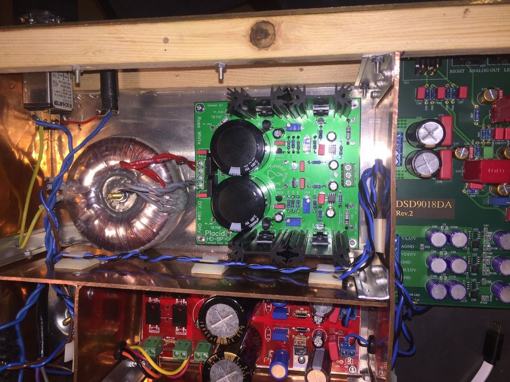 ]boards[/img]
|
|
|
|
|
|
Rank: Member
Groups: Member
Joined: 11/16/2015(UTC) Posts: 21 Location: İstanbul
|
Originally Posted by: avr300 Check for correct component placement and orientation.
First of all thanks for your assistance to help. From beginnig till end ; First I put all components for positive rail right hand Side of the table and components for negative rail left hand side of the table Then checked if the components are correct or not Than put all small components at their place before soldering again checked for placement and orientation After your recommendation I checked again placement and orientation and even component brand model no with lens , but no mistake All this makes me think faulty component There is no thermistor, as far as I know trimpots do not act az thermistor even if then are faulty , they pass or not they dont change themselves. I dont know, lost inside. :)
|
|
|
|
|
|
Rank: Member
Groups: Member
Joined: 11/16/2015(UTC) Posts: 21 Location: İstanbul
|
One other photo shut with lens 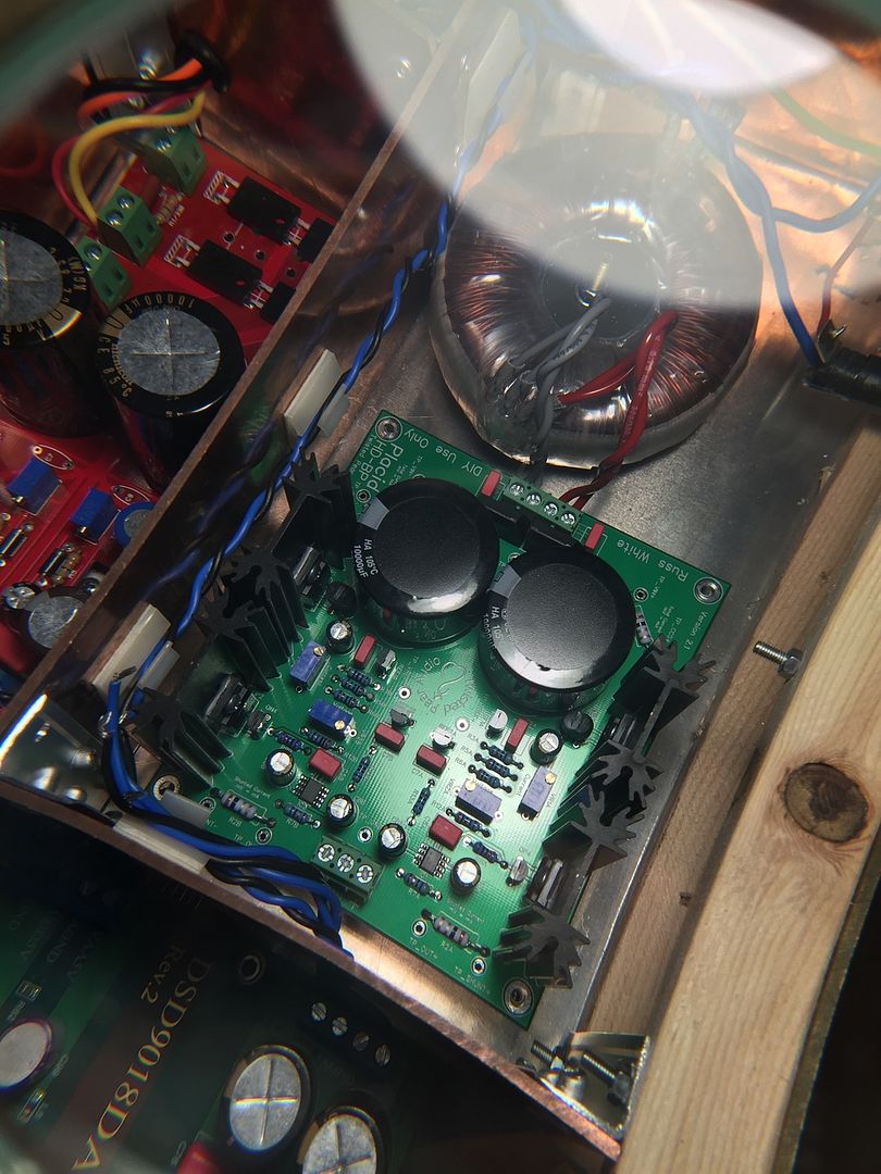
|
|
|
|
|
|
Rank: Member
Groups: Member
Joined: 11/16/2015(UTC) Posts: 21 Location: İstanbul
|
One more thing which recognized now.
When power is off;
I control both voltage VR, both works ok and I adjust both to 405 ohm.
Then power on;
CCS currents same 200 mA
Tp_vref for positive is 2,5v
Tp_vref for negative is 2,48v
Output voltage
Positive rail is 14,75 V
Negative rail is 6,5 V
Then try to adjust negative up to 14,75v but it fluctuates to much when I adjust to 14,75 V then Voltage VR is somewhere 1200 ohm something, and still -14,75 increases ,76 ; ,77 ; ,78 slowly.
|
|
|
|
|
|
Rank: Member
Groups: Member
Joined: 11/16/2015(UTC) Posts: 21 Location: İstanbul
|
This morning made 2 more measurements 1 ground to vr2 positive 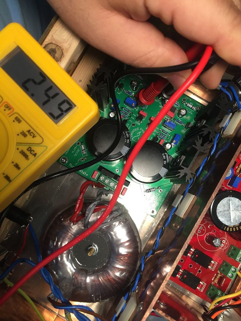 2 ground to vr2 negative 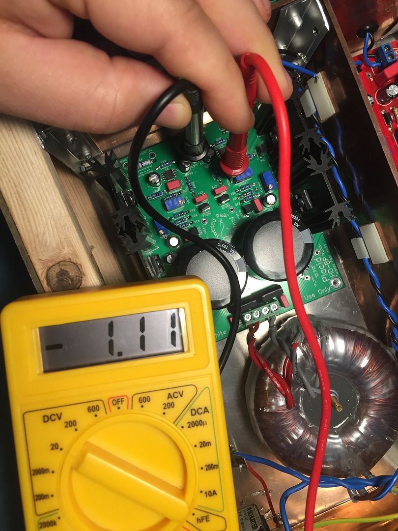
|
|
|
|
|
|
Rank: Member
Groups: Member
Joined: 6/17/2008(UTC) Posts: 921 Thanks: 1 times
Was thanked: 70 time(s) in 69 post(s)
|
Hi.
Try measure voltage between TP_VREF- and GND
|
|
|
|
|
|
Rank: Member
Groups: Member
Joined: 11/16/2015(UTC) Posts: 21 Location: İstanbul
|
Originally Posted by: avr300 Hi.
Try measure voltage between TP_VREF- and GND They are 2.48 and 2.49 Yesterday it was 2.48 today 2.49 measured Edited by user Sunday, January 17, 2016 10:26:54 AM(UTC)
| Reason: Not specified
|
|
|
|
|
|
Rank: Member
Groups: Member
Joined: 6/17/2008(UTC) Posts: 921 Thanks: 1 times
Was thanked: 70 time(s) in 69 post(s)
|
Excellent. Next step, follow the vref voltage all the way to the opamp.  cut170116-1.jpg (32kb) downloaded 26 time(s).ok or not ? . Edited by user Sunday, January 17, 2016 10:37:14 AM(UTC)
| Reason: Not specified
|
|
|
|
|
|
Rank: Member
Groups: Member
Joined: 11/16/2015(UTC) Posts: 21 Location: İstanbul
|
Originally Posted by: avr300 Excellent. Next step, follow the vref voltage all the way to the opamp. cut170116-1.jpg (32kb) downloaded 26 time(s).ok or not ? . We are now on the spot :) Tpvref -2.49 R13B 2 ... -2.49 R13B 1 ... -2.49 C8B - ... -2.49 IC2 3 ... - 0.99 (when I just touch the spot. Decreases and stops at -0.92 v) On the positive rail IC1 3 ... +2.49
|
|
|
|
|
|
Rank: Member
Groups: Member
Joined: 6/17/2008(UTC) Posts: 921 Thanks: 1 times
Was thanked: 70 time(s) in 69 post(s)
|
Hmm. Bad solder joint at opamp pin3 ? Do you have a fine tipped solder iron? If so, give pin3 a quick heat. . Edited by user Sunday, January 17, 2016 12:52:15 PM(UTC)
| Reason: spelling
|
|
|
|
|
|
Rank: Member
Groups: Member
Joined: 11/16/2015(UTC) Posts: 21 Location: İstanbul
|
Originally Posted by: avr300 Hmm. Bad solder joint at opamp pin3 ?
Do you have a fine tipped solder iron?
If so, give pin3 a quick heat.
. Did not solved, I could not managed I guess Thanks for your help. Will try to find someone to touch there Hope I will be able to solve.
|
|
|
|
|
|
Rank: Member
Groups: Member
Joined: 6/17/2008(UTC) Posts: 921 Thanks: 1 times
Was thanked: 70 time(s) in 69 post(s)
|
Ok, please do report your findings here.
I'm sure its solvable.
|
|
|
|
|
|
Rank: Member
Groups: Member
Joined: 11/16/2015(UTC) Posts: 21 Location: İstanbul
|
Hopefully if there is nothing with opamp then it shall be solved. I was planning to listen my new dac built it will be post poned :(    Edited by user Sunday, January 17, 2016 1:35:31 PM(UTC)
| Reason: Not specified
|
|
|
|
|
|
Rank: Member
Groups: Member
Joined: 6/17/2008(UTC) Posts: 921 Thanks: 1 times
Was thanked: 70 time(s) in 69 post(s)
|
If you do have -2,49 at C8, Quote:
C8B - ... -2.49
IC2 3 ... - 0.99
then you also need to have -2,49 at the pad where pin3 is supposed to make contact - it only one single track on the PCB. cut170116-3.jpg (25kb) downloaded 21 time(s).Get hold of your magnifying glass ;-) We need to get this running so you can listen.
|
|
|
|
|
|
Forum Jump
You cannot post new topics in this forum.
You cannot reply to topics in this forum.
You cannot delete your posts in this forum.
You cannot edit your posts in this forum.
You cannot create polls in this forum.
You cannot vote in polls in this forum.

