Twisted Pear Audio Support
»
User Galleries
»
Project Gallery
»
Buffalo III *now* Dual Mono Build / Denon DVD-3910 Mod
Rank: Member
Groups: Member
Joined: 9/16/2011(UTC)
Posts: 85
Location: Wisconsin
Thanks: 1 times
|
Rich,
That is one sharp looking DAC. I really like the faceplate. Thanks for sharing the various things you did!
MArk
|
|
|
|
|
|
Rank: Member
Groups: Member
Joined: 1/6/2012(UTC)
Posts: 305
Location: Plainfield, IL
Thanks: 11 times
Was thanked: 26 time(s) in 21 post(s)
|
Thanks for the kind words Mark! I am so glad I went with the Arduino/remote control. I had a lot of help from the folks here to make it all work. |
|
|
|
|
|
|
Rank: Member
Groups: Member
Joined: 1/19/2011(UTC)
Posts: 332
Location: Oslo, Norway
Thanks: 14 times
Was thanked: 17 time(s) in 17 post(s)
|
Thanks for the tip about svideo cables. I have no idea how many of those I have lying around. As well as proper scart cables from back in the day. I will have to have a closer look at those leads to see if they are salvagable for other purposes. All video signals are sent with HDMI, displayport and DVI here so no need for old "analog" video cables anymore.
|
|
|
|
|
|
Rank: Member
Groups: Member
Joined: 8/17/2010(UTC)
Posts: 368
Location: australia
Thanks: 8 times
Was thanked: 3 time(s) in 3 post(s)
|
I'm glad to hear the Amanero works fine stand alone mine may end up that way who can tell at this stage. I might start stand alone then add the reclocker to see what happens. I am just starting to modify the latest HiFiduino code to suit my setup & the BIII SE, I was wondering what standard changes you had to make going from the BII to BIII code, or if your ok to send me your latest code I can go thru it & pick out the changes. Edited by user Tuesday, January 29, 2013 10:54:17 AM(UTC)
| Reason: Not specified
|
|
|
|
|
|
Rank: Member
Groups: Member
Joined: 2/1/2012(UTC)
Posts: 332
Location: The Netherlands
Thanks: 4 times
Was thanked: 18 time(s) in 18 post(s)
|
Rich does not have the BIIISE, his spdif input switching is different to yours. I don't know your exact setup, but you have SPDIF on input D1, just like the BII has. You have to pull I_PS at the DAC board LOW or HIGH to switch between PCM/DSD or SPDIF. When you are using the OTTO II too than you need to switch this too by puling 'S' HIGH or LOW to switch between the sources hooked up to the OTTO. So that's what you should focucs on. I re-wrote large parts of the hifiduino code for Rich, and it's of no use for the BIIISE when it comes to input switching. I finished some code for a guy from Croatia two weeks ago. He has the BIIISE in dual mono, two SPDIF sources connected to the SPDIF comperator at D1 and two PCM/DSD sources. He uses two OTTO's. One for switching between the SPDIF sources and one for switching between the PCM/DSD sources. The code I wrote for him allows switching between all these sources. You can even change input names with the remote, enable or disable sources and setup each input (spdif1, spdif2, PCM/DSD1 or PCMDSD2 + all other DAC settings) completely to your needs. It is a simplified version of the code I'm currently (still) working on, but it's almost finished. The code is too large to fit onto the Arduino uno. In fact it is specially written for my own controller. My controller has some extra features that don't come with an Arduino. http://www.ce-designs.ne...he-es9018-i2c-controllerHere's a previous preview of the UI |
|
|
|
|
|
|
Rank: Member
Groups: Member
Joined: 8/17/2010(UTC)
Posts: 368
Location: australia
Thanks: 8 times
Was thanked: 3 time(s) in 3 post(s)
|
I think I have the switching sorted out.
Are there any other bits I should know about?
I think the BIII & BIIISE are generally the same.
I assume the assignment of the DAC registers are the same when in Stereo mode.
|
|
|
|
|
|
Rank: Member
Groups: Member
Joined: 2/1/2012(UTC)
Posts: 332
Location: The Netherlands
Thanks: 4 times
Was thanked: 18 time(s) in 18 post(s)
|
Originally Posted by: DQ828  I think I have the switching sorted out.
Are there any other bits I should know about? you should set the address of each DAC according to Leon's manual. Originally Posted by: DQ828 I think the BIII & BIIISE are generally the same. That's correct, appart from the input switching. Originally Posted by: DQ828 I assume the assignment of the DAC registers are the same when in Stereo mode. The registers are the same, but the I2C address is not for one of the DAC's. |
|
|
|
|
|
|
Rank: Member
Groups: Member
Joined: 1/6/2012(UTC)
Posts: 305
Location: Plainfield, IL
Thanks: 11 times
Was thanked: 26 time(s) in 21 post(s)
|
Well no casualties... Dual mono, one Legato I/V output board. Just balanced out, R and L channel have separate Placid BP power supplies (Jumpers J1-J4 have been removed). No single ended out by choice for now. Pos to neg output terminals on each DAC connected together and fed to Legato. I didn't take a pic of that. What does it do? My impression, with the single board fully discrete out you still get all the detail but it seems to blend better. With two Legato output boards (using SE for balanced outs) it is kind of like a recipe where the individual ingredients stand out more. All depends on the presentation you prefer. I'm kind a diggin the discrete out. If I want SE out I guess I can always put a couple jumpers back in (like J3 & J4) and reconnect one BP in the middle. Digi Key order hasn't arrived so no resistors used between pos and neg of balanced out yet. Russ had suggested in another dual mono single Legato post.. "I use the Legato with stock values and then add a 392-680R across + and - at the balanced output. This will lower the output back down to 2VRMs. It also reduces THD+N. This configuration sounds superb. 392R will get you a bit less than 2VRMs while 680R more." EDIT: For the sharp eyes, yes, GND is not connected at the Legato for balanced out. My Krell pre doesn't care about a balanced GND, works and still sounds the same. Strange, I can't seem to measure any common mode DC between the GND and + or - of the balanced out like I had with a single build. Or my sinus headache has me probing the wrong terminals... Edited by user Saturday, February 9, 2013 7:09:23 PM(UTC)
| Reason: Not specified SCompRacer attached the following image(s):  dualmono_singlelegato.jpg (209kb) downloaded 117 time(s).You cannot view/download attachments. Try to login or register. |
|
|
|
|
|
|
Rank: Member
Groups: Member
Joined: 1/6/2012(UTC)
Posts: 305
Location: Plainfield, IL
Thanks: 11 times
Was thanked: 26 time(s) in 21 post(s)
|
I added an OTTO II to my DAC to switch between USB to I2S and the Denon I2S/DSD input to the Sidecar. I'll control it with the Arduino/HiFiDuino/Corpius code. Still need to modify that code for the OTTO II. After opening Arduino software the cold sweat and shakes started so another day for that. Not sure if it was designed to fit like this but a female header and short cut off leads from a recent Krell pre amp recapping connect it to the Sidecar header pins. Mounting holes line up too, looks like a well thought out design plan. I kept the existing coax leads as they were working just fine. Great design skills or plain luck that the Teleporter mounting/harness length was just long enough. Luck is where preparation meets opportunity; blind luck is the absence of….. Edited by user Sunday, February 10, 2013 6:05:40 AM(UTC)
| Reason: Not specified SCompRacer attached the following image(s): otto_2sm.jpg (215kb) downloaded 83 time(s). otto_1sm.jpg (225kb) downloaded 93 time(s).You cannot view/download attachments. Try to login or register. |
|
|
|
|
|
|
Rank: Member
Groups: Member
Joined: 1/6/2012(UTC)
Posts: 305
Location: Plainfield, IL
Thanks: 11 times
Was thanked: 26 time(s) in 21 post(s)
|
Since pin 7 on the Arduino UNO does not completely go to zero volts (reads .009v when set to LOW) the OTTO II would remain switched to input 2. I made a small relay board to switch OTTO between my Denon and USB to I2S module. Now zero volts to S on OTTO II when Arduino pin LOW so it switches to input 1 when off. I am using HiFiDuino/Corpius modified code. Setting I2S for the source switches Sidecar HIGH. I added code to switch OTTO HIGH and LOW based on input selected (Denon I2S out and Amanero USB to I2S module). Worked great as long as I turned the encoder clockwise or used remote in CW source selection. If I went CCW (counter clockwise), the OTTO would remain high until I got to the LOW command. This is how I fixed it; add digitalWrite(OTTOPIN, LOW); to all other menu selections except for Denon input. Now I can turn encoder or use remote selecting inputs in either direction and it works properly. This code is located under: void setAndPrintInput(byte value) case 0: digitalWrite(OTTOPIN, HIGH); //Switch OTTO HIGH to select the Denon. LOW for USB lcd.print(no0); break; case 1: digitalWrite(OTTOPIN, LOW); lcd.print(no1); break; case 2: digitalWrite(OTTOPIN, LOW); lcd.print(no2); break; case 3: digitalWrite(OTTOPIN, LOW); lcd.print(no3); break; case 4: digitalWrite(OTTOPIN, LOW); lcd.print(no4); break; case 5: digitalWrite(OTTOPIN, LOW); lcd.print(no5); break; EDIT: After looking at it here, I could have just put a LOW command in the input on either side of the Denon input. Denon input is case 0, so put LOW command in case 1 and 5. But this is what happens when you are in over your head with code...you grasp and hold on to any solution that works....; ) Edited by user Saturday, February 23, 2013 11:02:51 PM(UTC)
| Reason: Not specified SCompRacer attached the following image(s): relay.jpg (196kb) downloaded 60 time(s).You cannot view/download attachments. Try to login or register. |
|
|
|
|
|
|
Rank: Member
Groups: Member
Joined: 1/6/2012(UTC)
Posts: 305
Location: Plainfield, IL
Thanks: 11 times
Was thanked: 26 time(s) in 21 post(s)
|
New configuration. Phase issue corrected with dual BIII/single Legato harness hook up. Still low output with two BIII/single Legato. No resistors between pos and neg of balanced out. Only measure .888mV between pos and neg of balanced out, DAC full volume playing test tone connected to pre amp. Legato is built with supplied parts. Legato is powered by two Placid BP's. One powers left channel; the other powers right channel and SE section (jumpers in J3 and J4 only). GND is now connected on balanced out. Four 1.0uf Metalized film caps used as coupling caps on pos/neg output of balanced. (That is all Radio Shack had; 2.0uf gen 1 Sonicaps will be ordered next week). While my pre worked with balanced GND disconnected, I got nasty pops when changing between sources. I also tried it with a friends balanced pre and it didn't like the balanced GND lifted. He wants a BIII/Legato so time for coupling caps. With balanced GND connnected, I can switch sources without muting. Sounds good, no complaints; only concern is not seeing higher output voltage. Edited by user Monday, March 4, 2013 7:08:48 AM(UTC)
| Reason: Not specified SCompRacer attached the following image(s): both_harness.jpg (73kb) downloaded 39 time(s). newconfig.jpg (188kb) downloaded 103 time(s).You cannot view/download attachments. Try to login or register. |
|
|
|
|
|
|
Rank: Member
Groups: Member
Joined: 8/17/2010(UTC)
Posts: 368
Location: australia
Thanks: 8 times
Was thanked: 3 time(s) in 3 post(s)
|
Originally Posted by: SCompRacer New configuration. Phase issue corrected with dual BIII/single Legato harness hook up. Still low output with two BIII/single Legato. No resistors between pos and neg of balanced out. Only measure .888mV between pos and neg of balanced out, DAC full volume playing test tone connected to pre amp. Legato is built with supplied parts.
Legato is powered by two Placid BP's. One powers left channel; the other powers right channel and SE section (jumpers in J3 and J4 only).
GND is now connected on balanced out. Four 1.0uf Metalized film caps used as coupling caps on pos/neg output of balanced. (That is all Radio Shack had; 2.0uf gen 1 Sonicaps will be ordered next week). While my pre worked with balanced GND disconnected, I got nasty pops when changing between sources. I also tried it with a friends balanced pre and it didn't like the balanced GND lifted. He wants a BIII/Legato so time for coupling caps. With balanced GND connnected, I can switch sources without muting.
Sounds good, no complaints; only concern is not seeing higher output voltage. I'd love to help but got nothing I'm afraid other than a question, how are you posting your photos.
|
|
|
|
|
|
Rank: Administration
Groups: Administration, Customer
Joined: 10/24/2006(UTC)
Posts: 2,869
Location: Massachusetts, USA
Thanks: 2 times
Was thanked: 141 time(s) in 134 post(s)
|
Quote:how are you posting your photos. When creating a post, there is a checkbox (see attachment). You can also attach pictures to an existing post by clicking the Attach button (see second attachment). Brian Donegan attached the following image(s): Untitled.png (6kb) downloaded 22 time(s). Untitled1.png (5kb) downloaded 8 time(s).You cannot view/download attachments. Try to login or register.
|
|
|
|
|
|
Rank: Member
Groups: Member
Joined: 1/6/2012(UTC)
Posts: 305
Location: Plainfield, IL
Thanks: 11 times
Was thanked: 26 time(s) in 21 post(s)
|
The last issue I had to correct on my dual mono DAC was to get it to play DSD in stereo instead of mono. While Russ came up with a great fix for dual mono BIII's to play in stereo in the thread link below, I could not see how to make it work with my multiple DSD inputs (USB to DSD and modded Denon 3910 exporting DSD) and SPDIF/Sidecar. http://www.twistedpearau...ono-configuration.aspx?=For better or worse, here is my solution. I used two switching relays like the ones TP uses on the Sidecar. I also copied the transistor/diode flyback circuit. Hope that was OK! (I did find pics on internet with similar flyback fix). It works great, DSD plays in stereo. No added noise floor or SQ loss that I can detect. For now I use a toggle switch on back of DAC to power relays. This is offered as an alternate solution for folks having a dual mono DAC of similar configuration. 2-5 is jumpered under relay. The unbroken circuits D1 for Left channel DAC board and D2 for Right channel DAC board, I just carefully stripped 1/8" of insulation off wire without cutting it in half and soldered it to terminal 6 of relay. PCM plays, circuit is complete via 2-3-5. When relays powered to play DSD, 2-3 opens to open circuit from source, 5-6 close so Left channel gets only Left input on D1 and D2 and Right channel gets only Right input on D1 and D2. Edited by user Sunday, September 15, 2013 9:02:13 PM(UTC)
| Reason: Not specified SCompRacer attached the following image(s): biiidualmono_dsdfix_7.jpg (45kb) downloaded 51 time(s). Relay driver.jpg (37kb) downloaded 24 time(s). biiidualmono_dsdfix_1.JPG (100kb) downloaded 21 time(s). biiidualmono_dsdfix_2.JPG (146kb) downloaded 21 time(s). biiidualmono_dsdfix_3.JPG (157kb) downloaded 22 time(s).You cannot view/download attachments. Try to login or register. |
|
|
|
|
|
|
Rank: Member
Groups: Member
Joined: 1/6/2012(UTC)
Posts: 305
Location: Plainfield, IL
Thanks: 11 times
Was thanked: 26 time(s) in 21 post(s)
|
Couple more pics... Edited by user Sunday, September 15, 2013 5:16:20 AM(UTC)
| Reason: Not specified SCompRacer attached the following image(s): biiidualmono_dsdfix_4.JPG (95kb) downloaded 30 time(s). biiidualmono_dsdfix_6.jpg (196kb) downloaded 135 time(s).You cannot view/download attachments. Try to login or register. |
|
|
|
|
|
|
Rank: Administration
Groups: Administration, Customer
Joined: 10/24/2006(UTC)
Posts: 3,979
Location: Nashville, TN
Thanks: 25 times
Was thanked: 89 time(s) in 83 post(s)
|
One to remember is that it's not really a "fix" - as nothing was broken. :) It is just the way the ESS chip is designed to operate.
BTW, it would be very simple to implement that using the OTTO-II.
|
|
|
|
|
|
Rank: Member
Groups: Member
Joined: 1/6/2012(UTC)
Posts: 305
Location: Plainfield, IL
Thanks: 11 times
Was thanked: 26 time(s) in 21 post(s)
|
|
|
|
|
|
|
|
Rank: Member
Groups: Member
Joined: 2/1/2012(UTC)
Posts: 332
Location: The Netherlands
Thanks: 4 times
Was thanked: 18 time(s) in 18 post(s)
|
Nice build Rich. Real eye candy! I really need to start a project like this myself again. |
|
|
|
|
|
|
Rank: Member
Groups: Member
Joined: 1/19/2011(UTC)
Posts: 332
Location: Oslo, Norway
Thanks: 14 times
Was thanked: 17 time(s) in 17 post(s)
|
Love your builds. Looks great and informative for someone who is entering the world of DSD/I2S switchable playback.
I just have one little question that I am thinking about;
Why have the DSD/PCM (I2S) otto2 inside the Denon case?
Would it not work if you had that switch inside the DAC case where the arduino is?
The reason I am asking leads to a follow up question;
Will the DAC (arduino) recognize the signal as a DSD signal even if the lines are not switched?
If so the arduino could send a signal whenever the display states that it has a DSD signal and then switch the otto2 ;)
|
|
|
|
|
|
Rank: Member
Groups: Member
Joined: 1/6/2012(UTC)
Posts: 305
Location: Plainfield, IL
Thanks: 11 times
Was thanked: 26 time(s) in 21 post(s)
|
Originally Posted by: gwikse Love your builds. Looks great and informative for someone who is entering the world of DSD/I2S switchable playback.
I just have one little question that I am thinking about;
Why have the DSD/PCM (I2S) otto2 inside the Denon case?
Would it not work if you had that switch inside the DAC case where the arduino is?
The reason I am asking leads to a follow up question;
Will the DAC (arduino) recognize the signal as a DSD signal even if the lines are not switched?
If so the arduino could send a signal whenever the display states that it has a DSD signal and then switch the otto2 ;) Thanks for the kind words! My Swiss army knife approach with inputs was due in part both to necessity and digital ignorance at the time. Kind of long winded but here goes. The OTTO II was installed in the Denon to switch Right and Left channels of DSD that shared same lines as I2S out. I used a manual switch. In the DAC I already had the Sidecar to switch between SPDIF and I2S along with OTTO to switch between Denon input and USB input controlled by Arduino. Dual mono complicated things further as it would play DSD in mono if you didn't perform an input remap with DSD which I performed with signal relays. If it were stereo only, I could just ignore the Amanero DSD channel swap and the Denon channel swap would be corrected. If the OTTO for channel reversal were installed in the DAC, I could have used automatic switching, but it was busy enough in there. ;) At that time we had regular music meets where folks would bring CD's/SACD's. Now folks bring music on thumb drives and vinyl, so the Denon sits unused. With the improved USB to I2S modules available, USB input sounds much better than SPDIF input to me. So I went for input simplicity. I don't use SPDIF and removed the Sidecar. I also removed the Teleporter for the Denon and OTTO. Currently I have the Sonore USB to I2S module. It was purchased at a reduced price due to no markings on the board way before TP released their Hermes/Cronus solution. I purchased a Hermes/Cronus for a friends DAC and did test it in my DAC. I could not tell any sonic difference between the two running in async. Until I sort out the right DAC board issues, I have returned to a single BIII. Much simpler! I also tried and like running in sync using Ian of FIFO fame BIII adapters. With the version 1.0.2 DAC board, I installed a two pin female header on the DAC clock connections. I used an Ian clock adapter board that comes with the U.fl header adapter. I installed two 90 degree male pins to plug into the DAC clock female header. Remove the Trident for clock to run in sync. Sync would be more difficult to implement with dual mono using U.fl connectors. No one makes a U.fl Y connector. 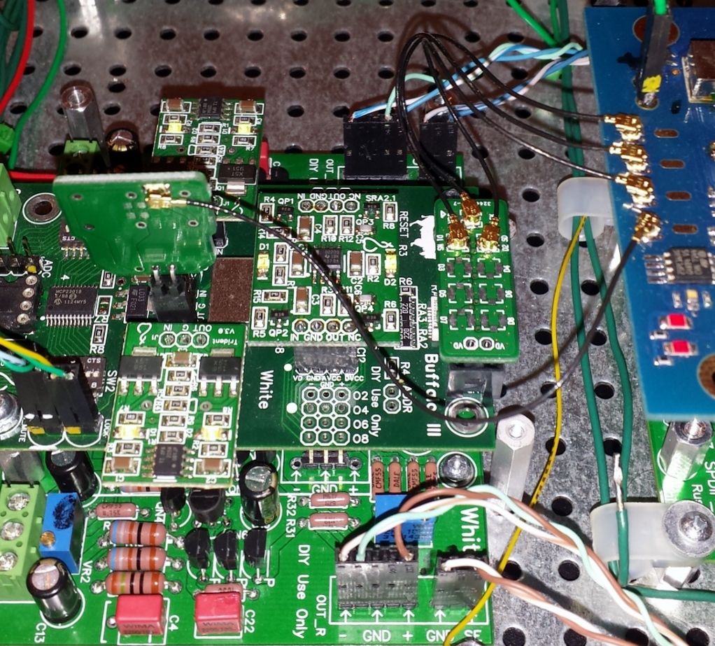 For the version 1.0.1 BIII DAC, I attached the two pin header on clock connections under the board. Once I get the DC issue sorted on this DAC I can test it and try sync in dual mono. Ian suggests removing the clock off the BIII and attaching it to his board via plug in board and solder adapter into board. You remove the clock to run in sync. But I prefer this method where I unplug the board and put the Tridnet powering the clock back in. I only have a simple solder iron station. Without a proper desolder tool to remove the clock I'd probably destroy it. I purchased four sets of the BIII adapters from Ian. He still has some left, don't know if he will have anymore made if they are gone. I made an adapter out of a female pin header, but it provided no support under the center pin. U.fl's are meant to be installed on a flat PCB. 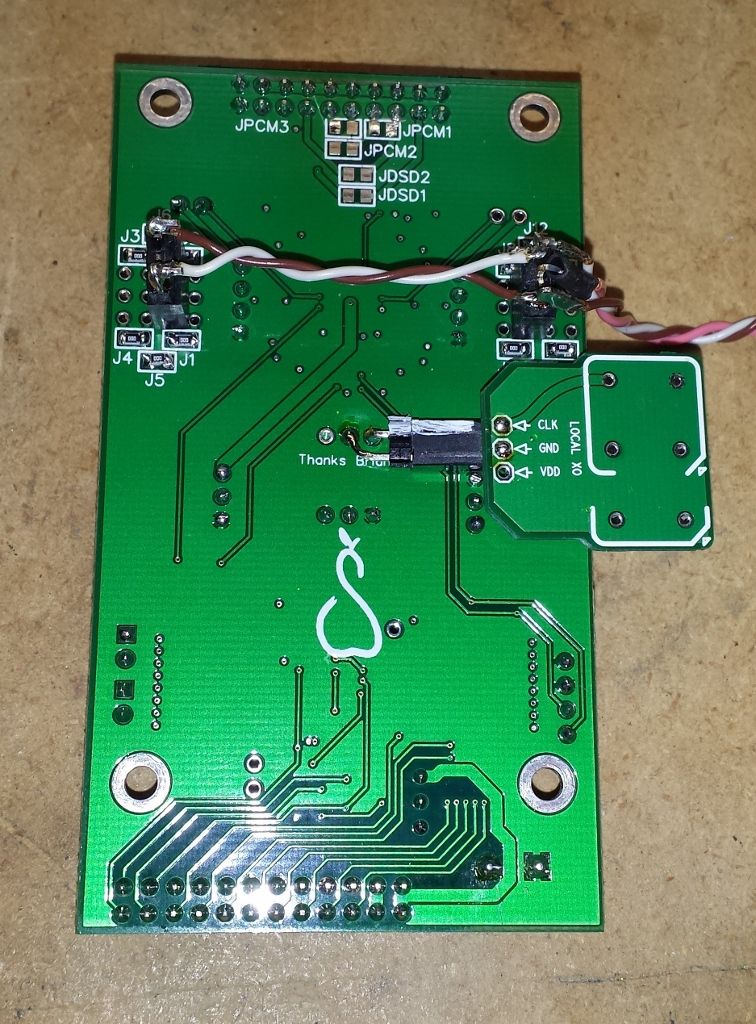 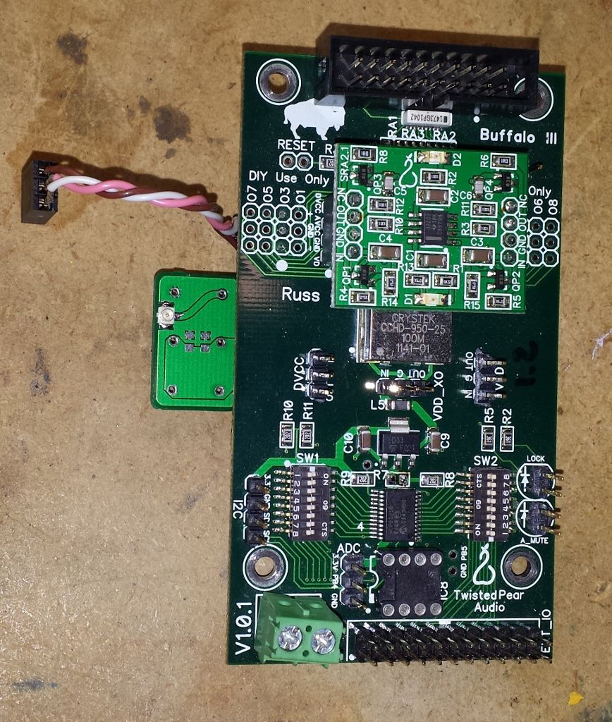 Edited by user Tuesday, March 15, 2016 5:05:28 PM(UTC)
| Reason: Not specified |
|
|
|
|
|
|
Twisted Pear Audio Support
»
User Galleries
»
Project Gallery
»
Buffalo III *now* Dual Mono Build / Denon DVD-3910 Mod
Forum Jump
You cannot post new topics in this forum.
You cannot reply to topics in this forum.
You cannot delete your posts in this forum.
You cannot edit your posts in this forum.
You cannot create polls in this forum.
You cannot vote in polls in this forum.

