Rank: Member
Groups: Member
Joined: 7/6/2008(UTC)
Posts: 27
Location: uk
|
Hi, is there a wiring diagram available that i can look at? I need to hook up my balanced jtree kit with my balanced inputs and un balanced inputs using an otto.
Thank you.
|
|
|
|
|
|
Rank: Administration
Groups: Administration, Customer
Joined: 10/24/2006(UTC)
Posts: 2,869
Location: Massachusetts, USA
Thanks: 2 times
Was thanked: 141 time(s) in 134 post(s)
|
Here is a quick diagram for wiring up the signals into and out of the relay boards for balanced use: Brian Donegan attached the following image(s):  Balanced_JT_Wiring.JPG (37kb) downloaded 1,003 time(s).You cannot view/download attachments. Try to login or register.
|
|
|
|
|
|
Rank: Advanced Member
Groups: Member
Joined: 5/6/2009(UTC)
Posts: 38
Location: san francisco
|
Is it safe to assume the jumper is there for both boards in balanced use?
|
|
|
|
|
|
Rank: Administration
Groups: Administration, Customer
Joined: 10/24/2006(UTC)
Posts: 2,869
Location: Massachusetts, USA
Thanks: 2 times
Was thanked: 141 time(s) in 134 post(s)
|
Yes. The jumper causes the ground to be shared by both the + and - sides, so that both signals are referenced to the same ground. It is equivalent to using a jumper wire between the IN GND positions in the terminal blocks.
For single-ended use, you can leave the jumper out for separate left-right grounds, or use it if you have (or to create*) a shared ground.
*Creating a shared ground at the JT is not recommended unless you know what you are doing to avoid possible ground loops.
|
|
|
|
|
|
Rank: Advanced Member
Groups: Member
Joined: 2/8/2007(UTC)
Posts: 21
Location: Bakersfield Ca
|
Brian,
Your diagram above show the + signal going to the gnd and gnd going to input of one side of board is that correct?
Bill
|
|
|
|
|
|
Rank: Administration
Groups: Administration, Customer
Joined: 10/24/2006(UTC)
Posts: 3,979
Location: Nashville, TN
Thanks: 25 times
Was thanked: 89 time(s) in 83 post(s)
|
NO It is not correct. +IN(and out) and GND are swapped. Good catch. :) Edited by user Tuesday, May 12, 2009 7:04:44 PM(UTC)
| Reason: Not specified
|
|
|
|
|
|
Rank: Advanced Member
Groups: Member
Joined: 12/7/2008(UTC)
Posts: 47
Location: Netherlands
|
fault151 wrote:Hi, is there a wiring diagram available that i can look at? I need to hook up my balanced jtree kit with my balanced inputs and un balanced inputs using an otto.
Thank you. hope this is helpfull to you 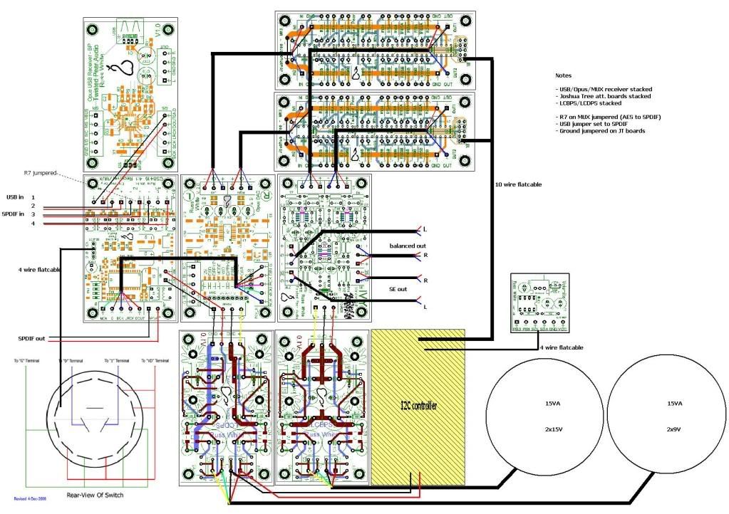
|
|
|
|
|
|
Rank: Advanced Member
Groups: Member
Joined: 5/6/2009(UTC)
Posts: 38
Location: san francisco
|
nevermind... question bad. Edited by user Thursday, June 4, 2009 8:22:23 AM(UTC)
| Reason: Not specified
|
|
|
|
|
|
Rank: Member
Groups: Member
Joined: 7/6/2008(UTC)
Posts: 27
Location: uk
|
When hooking up the wires to the joshua tree output posts in balanced mode, is it best to pair the + from both amplifier boards to the same jtree board and both the - amplifier boards to the other jtree board? Or does it not matter? Does that make sense?
For example:
b22 amplifier Right+ board connects to jtree board 1
b22 amplifier Left + board connects to jtree board 1
b22 amplifier Right - board connects to jtree board 2
b22 amplifier Left - board connects to jtree board 2
Thanks
|
|
|
|
|
|
Rank: Administration
Groups: Administration, Customer
Joined: 10/24/2006(UTC)
Posts: 3,979
Location: Nashville, TN
Thanks: 25 times
Was thanked: 89 time(s) in 83 post(s)
|
Use one JT relay board per channel. Both + and -.
You want to keep those signals close together.
Cheers!
Russ
|
|
|
|
|
|
Rank: Advanced Member
Groups: Member
Joined: 5/6/2009(UTC)
Posts: 38
Location: san francisco
|
are you supposed to tie the boards' grounds together? Also, I have 30V coming in from a sigma 22 PSU. Should I put a zener diode or maybe just a resistor in line with the wiring to pull the voltage down a bit? It works with the 30V, but it gets hot quickly and I don't want to burn out the onboard rectifier. Edited by user Monday, January 18, 2010 2:47:08 PM(UTC)
| Reason: Not specified
|
|
|
|
|
|
Rank: Administration
Groups: Administration, Customer
Joined: 10/24/2006(UTC)
Posts: 2,869
Location: Massachusetts, USA
Thanks: 2 times
Was thanked: 141 time(s) in 134 post(s)
|
I would chassis-mount the vreg if possible, or at the very least use a larger HS for it with 30V in.
|
|
|
|
|
|
Rank: Advanced Member
Groups: Member
Joined: 5/6/2009(UTC)
Posts: 38
Location: san francisco
|
I'm just going to go ahead and add a trafo. Also, for those trouble shooting their JTA's, I had a problem with one of my boards (I'm running a 2 board balanced setup) that turned out being fixed when I pushed the ribbon cable harder into the snap connector.
|
|
|
|
|
|
Forum Jump
You cannot post new topics in this forum.
You cannot reply to topics in this forum.
You cannot delete your posts in this forum.
You cannot edit your posts in this forum.
You cannot create polls in this forum.
You cannot vote in polls in this forum.

