Rank: Member
Groups: Member
Joined: 5/5/2016(UTC) Posts: 7  Thanks: 1 times
|
Hi guys,
I've recently built a Placid HD 2.1, but I'm having trouble setting the shunt current.
I'm using a 9V transformer. I've used a 1k82 resistor in place of VR2A. With no load attached to the placid, and VR1 set to 500R, I'm measuring 10.74V AC across the inputs and 5.23V DC across the outputs, so the voltage looks OK.
I'm measuring 12.67V at TP_VIN+ (with the probe ground connected to TP_GND2) and 12.64V at TP_CCS+. I'm getting 72mV across R1.
The trouble is, I can't get more than 250mV across R1 however I set VR1. I'm using this with a Buffalo II, so I'm aiming for 350mA shunt current.
I'd appreciate any tips for troubleshooting. I've checked my soldering, and can't see any poor joints / shorts.
Cheers,
Jon
|
|
|
|
|
|
Rank: Member
Groups: Member
Joined: 6/17/2008(UTC) Posts: 921  Thanks: 1 times
Was thanked: 70 time(s) in 69 post(s)
|
I'm here, I'll help you.
Can we see some good sharp pictures, front and back please.
We'll get it running ;-)
|
|
|
|
|
|
Rank: Member
Groups: Member
Joined: 5/5/2016(UTC) Posts: 7 Thanks: 1 times
|
Here are a few photos. Taken with poor lighting I'm afraid, but hopefully good enough.  3.jpg (61kb) downloaded 23 time(s). 2.jpg (54kb) downloaded 23 time(s). 1.jpg (74kb) downloaded 27 time(s). 4.jpg (85kb) downloaded 30 time(s).
|
|
|
|
|
|
Rank: Member
Groups: Member
Joined: 6/17/2008(UTC) Posts: 921 Thanks: 1 times
Was thanked: 70 time(s) in 69 post(s)
|
Originally Posted by: Jonwhitear 
The trouble is, I can't get more than 250mV across R1 however I set VR1. I'm using this with a Buffalo II, so I'm aiming for 350mA shunt current.
Measured with or without the load (Buffalo II) connected ?
|
|
|
|
|
|
Rank: Member
Groups: Member
Joined: 5/5/2016(UTC) Posts: 7 Thanks: 1 times
|
This is without a load connected.
|
|
|
|
|
|
Rank: Administration
Groups: Administration, Customer
Joined: 10/24/2006(UTC)
Posts: 2,869
Location: Massachusetts, USA
Thanks: 2 times
Was thanked: 141 time(s) in 134 post(s)
|
It is hard to tell for sure, but it looks like you have a few solder joints (mainly to ground, so harder to heat) that are "minarets," where the pads didn't get hit enjoying to flow well. Try adding a little flux to those and reflow.
Also, do you have thermal compound on your power transistors?
|
|
|
|
|
|
Rank: Member
Groups: Member
Joined: 5/5/2016(UTC) Posts: 7 Thanks: 1 times
|
Here are a few more photos. I have reflowed most of the solder joints before taking this set of photos. That did make a little difference - I can get an extra 5mV across R1! I do have thermal compound on the transistors. IMG_1674.jpg (268kb) downloaded 177 time(s). IMG_1673.jpg (323kb) downloaded 7 time(s). IMG_1678.jpg (332kb) downloaded 7 time(s). IMG_1679.jpg (232kb) downloaded 15 time(s).Cheers, Jon Edited by user Sunday, July 3, 2016 2:32:13 AM(UTC)
| Reason: Not specified
|
|
|
|
|
|
Rank: Administration
Groups: Administration, Customer
Joined: 10/24/2006(UTC)
Posts: 2,869
Location: Massachusetts, USA
Thanks: 2 times
Was thanked: 141 time(s) in 134 post(s)
|
If you measure resistance across VR1 (TH resistor pads), do you see the value changing while adjusting?
|
|
|
|
|
|
Rank: Member
Groups: Member
Joined: 5/5/2016(UTC) Posts: 7 Thanks: 1 times
|
Originally Posted by: Brian Donegan If you measure resistance across VR1 (TH resistor pads), do you see the value changing while adjusting? I do. With VR1 set to 500R, I get 72mV across R1. With it set to 0R, I get 254mV across R1.
|
|
|
|
|
|
Rank: Administration
Groups: Administration, Customer
Joined: 10/24/2006(UTC)
Posts: 2,869
Location: Massachusetts, USA
Thanks: 2 times
Was thanked: 141 time(s) in 134 post(s)
|
The problem is your voltage reference: LT1004 1.2V. You need a 2.5V reference. We use the LT1034-2.5V, though you can use the LT1004-2.5V.
|
|
|
|
|
|
Rank: Member
Groups: Member
Joined: 6/17/2008(UTC) Posts: 921 Thanks: 1 times
Was thanked: 70 time(s) in 69 post(s)
|
Just curious - what did I miss not seeing this earlier on ? . Edited by user Wednesday, July 6, 2016 7:38:34 PM(UTC)
| Reason: Not specified
|
|
|
|
|
|
Rank: Administration
Groups: Administration, Customer
Joined: 10/24/2006(UTC)
Posts: 2,869
Location: Massachusetts, USA
Thanks: 2 times
Was thanked: 141 time(s) in 134 post(s)
|
Originally Posted by: avr300 Just curious - what did I miss not seeing this earlier on ?
. I spotted it here after a strong cup of coffee... 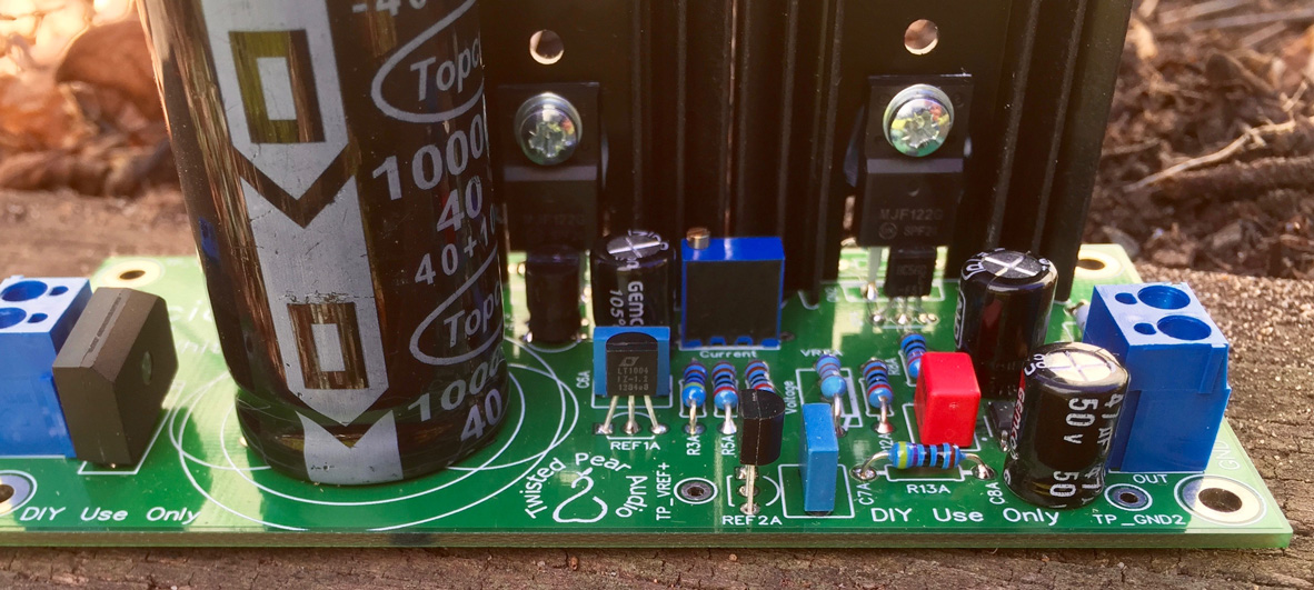 Edited by user Wednesday, July 6, 2016 9:08:15 PM(UTC)
| Reason: Not specified
|
 1 user thanked Brian Donegan for this useful post.
|
|
|
|
Rank: Member
Groups: Member
Joined: 5/5/2016(UTC) Posts: 7 Thanks: 1 times
|
Brian, avr300, thank you. I hadn't even considered that I might have the wrong parts. I just checked back through my records and found that I ordered two 2.5V references, but I've obviously been supplied two different parts, and hadn't checked them. I very much appreciate the time and effort you have put in to ensure I get this working.
Cheers,
Jon
|
|
|
|
|
|
Rank: Member
Groups: Member
Joined: 6/17/2008(UTC) Posts: 921 Thanks: 1 times
Was thanked: 70 time(s) in 69 post(s)
|
Originally Posted by: Brian Donegan Originally Posted by: avr300 Just curious - what did I miss not seeing this earlier on ?
. I spotted it here after a strong cup of coffee... And I completely missed that picture. Sorry. Good catch! Edited by moderator Thursday, July 7, 2016 6:11:58 PM(UTC)
| Reason: Not specified
|
|
|
|
|
|
Rank: Administration
Groups: Administration, Customer
Joined: 10/24/2006(UTC)
Posts: 3,979
Location: Nashville, TN
Thanks: 25 times
Was thanked: 89 time(s) in 83 post(s)
|
Wow - that was a great catch! :)
|
|
|
|
|
|
Forum Jump
You cannot post new topics in this forum.
You cannot reply to topics in this forum.
You cannot delete your posts in this forum.
You cannot edit your posts in this forum.
You cannot create polls in this forum.
You cannot vote in polls in this forum.

