Rank: Member
Groups: Member
Joined: 10/18/2012(UTC) Posts: 18  Location: Bucuresti Was thanked: 1 time(s) in 1 post(s)
|
Hi Guys,
I'm a little bit concerned about self generated noise of Trident 3.0 and AVCC SRA2.1 regulators.
There are any official numbers or this parameter was not one of the primary goals when those regulators were designed?
There is any reason why the regulator AC gain was not reduced to unity by putting a bypass capacitor (100-120uF) over feedback resistor, in order to reduce the noise?
Kind regards,
Mihai
|
|
|
|
|
|
Rank: Administration
Groups: Administration, Customer
Joined: 10/24/2006(UTC)
Posts: 3,979
Location: Nashville, TN
Thanks: 25 times
Was thanked: 89 time(s) in 83 post(s)
|
Concerned? No need to be it works very well. :)
The regulator is meant to regulate actively - it is a shunt regulator ultra low output impedance is critical. You would never want to place such a cap across the feedback as you would then lose AC load regulation - and it's just not a good thing to do to such a circuit.
You can always use something of your own design if you like. :D Use whatever parameters you choose. :)
|
|
|
|
|
|
Rank: Member
Groups: Member
Joined: 10/18/2012(UTC) Posts: 18 Location: Bucuresti Was thanked: 1 time(s) in 1 post(s)
|
Originally Posted by: Russ White  Concerned? No need to be it works very well. :)
The regulator is meant to regulate actively - it is a shunt regulator ultra low output impedance is critical. You would never want to place such a cap across the feedback as you would then lose AC load regulation - and it's just not a good thing to do to such a circuit.
You can always use something of your own design if you like. :D Use whatever parameters you choose. :) You are right, I'm not in position to suggest such things ... But, take a look here: http://www.linearaudio.n...pdf/superreg_article.pdf Do you believe Jung was not concerned about AC regulation when he put C3/C7 over feedback resistors on the super-regulator? The role of those capacitors are to reduce the output noise to the OPA noise level at any frequency over 1/f of the entire circuit.
|
|
|
|
|
|
Rank: Administration
Groups: Administration, Customer
Joined: 10/24/2006(UTC)
Posts: 3,979
Location: Nashville, TN
Thanks: 25 times
Was thanked: 89 time(s) in 83 post(s)
|
If you look closely you will note that C3 and C7 are not directly in parallel with the feedback to the error amp output. :)
In any case - that JSR is a completely different beast and the error amp operation is not really the same.
I don't mind the question - but I designed the AVCC for the task and I rather like it. :)
|
|
|
|
|
|
Rank: Member
Groups: Member
Joined: 10/18/2012(UTC) Posts: 18 Location: Bucuresti Was thanked: 1 time(s) in 1 post(s)
|
Originally Posted by: Russ White If you look closely you will note that C3 and C7 are not directly in parallel with the feedback to the error amp output. :)
They are exactly in parallel with the feedback resistors which connects with the inverted input of OPA ... Pin 1 and 2 should be connected together at the load in order to activate remote sensing. The same applies to pins 3 and 4.
|
|
|
|
|
|
Rank: Administration
Groups: Administration, Customer
Joined: 10/24/2006(UTC)
Posts: 3,979
Location: Nashville, TN
Thanks: 25 times
Was thanked: 89 time(s) in 83 post(s)
|
They are at the output/sense of the entire circuit to -IN - but not the output of the OPA (which is the error amp) :) Yes it does connect to the inverting input. I never said it didn't. In any case you are comparing a series regulator with a shunt regulator. Edited by user Thursday, December 4, 2014 4:20:41 PM(UTC)
| Reason: Not specified
|
|
|
|
|
|
Rank: Administration
Groups: Administration, Customer
Joined: 10/24/2006(UTC)
Posts: 3,979
Location: Nashville, TN
Thanks: 25 times
Was thanked: 89 time(s) in 83 post(s)
|
They are just fundamentally different circuits with fundamentally different needs. :) Plus the actual gain of the circuit is tiny - already near unity.
|
|
|
|
|
|
Rank: Member
Groups: Member
Joined: 3/8/2011(UTC)
Posts: 136
Location: Norway
Was thanked: 2 time(s) in 2 post(s)
|
I tried 47uf caps on AVCC out, and as Russ have said earlier, "this is not a good thing to do". If you want the Buffalo to perform at max, leave out the caps.
I've also tried caps on the Tridents, and that was even worse.
|
|
|
|
|
|
Rank: Member
Groups: Member
Joined: 10/18/2012(UTC) Posts: 18 Location: Bucuresti Was thanked: 1 time(s) in 1 post(s)
|
After few modifications I succeed to make my AVCC to perform really well, both Zout and self generated noise. Here are what I have modified: 1. OPA2211 instead of LMP7732 2. Reduced feedback resistors, 100 and 130 ohms instead of 1k and 1k3 3. Increased CCS current in order to compensate the loss of current over feedback resistors 4. Increased compensation capacitors from 100pF to 870pF Now I have measured 3.4nVrth from 100Hz to 100Khz which translates in only 1.09uVrms :-) Zout remains the same as unmodified version. Edited by user Thursday, January 1, 2015 2:51:20 PM(UTC)
| Reason: Not specified
|
 1 user thanked roender for this useful post.
|
|
|
|
Rank: Member
Groups: Member
Joined: 6/17/2008(UTC) Posts: 921  Thanks: 1 times
Was thanked: 70 time(s) in 69 post(s)
|
Originally Posted by: roender
..
Now I have measured 3.4nVrth from 100Hz to 100Khz which translates in only 1.09uVrms :-)
Zout remains the same as unmodified version.
Do you have identical measures of the unmodified version ?
|
|
|
|
|
|
Rank: Member
Groups: Member
Joined: 10/18/2012(UTC) Posts: 18 Location: Bucuresti Was thanked: 1 time(s) in 1 post(s)
|
Yes:
V OUT Noise (nV rtHz) 10.6
V OUT Noise RMS (uV B=100Khz) 3.4
|
|
|
|
|
|
Rank: Member
Groups: Member
Joined: 10/18/2012(UTC) Posts: 18 Location: Bucuresti Was thanked: 1 time(s) in 1 post(s)
|
The biggest improvement comes from modified clock's trident. Edited by user Friday, January 2, 2015 12:55:30 PM(UTC)
| Reason: Not specified
|
|
|
|
|
|
Rank: Member
Groups: Member
Joined: 10/22/2011(UTC)
Posts: 135
Location: Prague
Thanks: 1 times
Was thanked: 3 time(s) in 3 post(s)
|
roender: do you have some special meter for this or is it possible to measure it with standard measurement tools (and/or soundcard) ? thanks.
|
|
|
|
|
|
Rank: Member
Groups: Member
Joined: 10/18/2012(UTC) Posts: 18 Location: Bucuresti Was thanked: 1 time(s) in 1 post(s)
|
You can not use a simple DMM.
For noise measurements I used a true RMS meter (HP3458A) and a very low noise instrumentation amplifier.
|
|
|
|
|
|
Rank: Administration
Groups: Administration, Customer
Joined: 10/24/2006(UTC)
Posts: 2,869
Location: Massachusetts, USA
Thanks: 2 times
Was thanked: 141 time(s) in 134 post(s)
|
To be clear, this is for an older AVCC (two generations ago) with the LMP7732 opamp.
|
|
|
|
|
|
Rank: Member
Groups: Member
Joined: 8/22/2010(UTC) Posts: 38  Thanks: 14 times
|
Originally Posted by: roender
1. OPA2211 instead of LMP7732
2. Reduced feedback resistors, 100 and 130 ohms instead of 1k and 1k3
3. Increased CCS current in order to compensate the loss of current over feedback resistors
4. Increased compensation capacitors from 100pF to 870pF
Did you modify the AVCC SRA 2 V-1.0 version? Will you share the board part numbers replaced in #1-3 above? I upgraded my AVCC (SRA2 V-1.0) with OPA2209 (pictured below) and Trident v1.1 with OPA209, but I did not modify any capacitors or resistors ( Russ's post on opamp upgrade.). 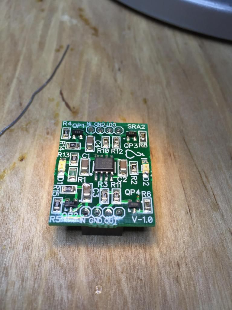
|
|
|
|
|
|
Rank: Member
Groups: Member
Joined: 10/18/2012(UTC) Posts: 18 Location: Bucuresti Was thanked: 1 time(s) in 1 post(s)
|
Originally Posted by: Brian Donegan To be clear, this is for an older AVCC (two generations ago) with the LMP7732 opamp. From noise point of view, doesn't mater which version you have as long as feedback resistors was not changed (1k and 1k3) As you can see from the attached XLS file, the output noise is dominated by feedback resistors and not the OPA, so just changing LMP7732 with OPO2209 didn't change much the regulator output noise. Other AVCC's components do not practically contribute to noise figure. Measured noise confirmed the calculated values showed into the attached file. File Attachment(s):  AVCC Reg Noise.xls (32kb) downloaded 12 time(s).You cannot view/download attachments. Try to login or register.
|
|
|
|
|
|
Rank: Administration
Groups: Administration, Customer
Joined: 10/24/2006(UTC)
Posts: 3,979
Location: Nashville, TN
Thanks: 25 times
Was thanked: 89 time(s) in 83 post(s)
|
Actually it does matter quite a lot - because the voltage reference is completely different with different impedance.
|
|
|
|
|
|
Rank: Administration
Groups: Administration, Customer
Joined: 10/24/2006(UTC)
Posts: 3,979
Location: Nashville, TN
Thanks: 25 times
Was thanked: 89 time(s) in 83 post(s)
|
I do agree that lower value resistors will get you a (albeit very small) reduction in noise - but it come at the cost of more current loss and a bit less safety margin. Still it is a very simple DIY change if one has the mind to do it. :)
|
|
|
|
|
|
Rank: Member
Groups: Member
Joined: 10/18/2012(UTC) Posts: 18 Location: Bucuresti Was thanked: 1 time(s) in 1 post(s)
|
Originally Posted by: Russ White Actually it does matter quite a lot - because the voltage reference is completely different with different impedance. From noise POV it's not an improvement but I agree that shunt regulator Zout can be lowered with a voltage reference with very low Zout. In fact, ideally is to have a voltage reference with very low Zout and in the same time very low noise. I have not yet seen a reference with less noise than a red or green LED.
|
|
|
|
|
|
Forum Jump
You cannot post new topics in this forum.
You cannot reply to topics in this forum.
You cannot delete your posts in this forum.
You cannot edit your posts in this forum.
You cannot create polls in this forum.
You cannot vote in polls in this forum.

