Welcome Guest! To enable all features please Login or Register.

Notification

Icon
Error

Login


Options
View
Go to last post Go to first unread
Adastra  
#1 Posted : Tuesday, May 15, 2012 5:02:49 PM(UTC)
Adastra

Rank: Member

Groups: Member
Joined: 3/13/2012(UTC)
Posts: 22

Was thanked: 3 time(s) in 2 post(s)
Ok, feels good to be done, at least until I start adding stuff! Nothing too revolutionary to you experts I'm sure, but its making me happy. Turned out great for a beginner. Prior to this I'd done a Bottlehead Seduction, a few step-up transformers, and lots of music industry projects for my day job, but this was definitely my most ambitious HiFi project to date.
Anyway here's pics!
UserPostedImage
Used a Par-Metal 16x12x3 20-series case, and was very satisfied with the quality. Might do a FPE fancy panel at some point, but we'll see, I might do an Arduino panel eventually, but right now its pretty simple: power, source on the left, volume on the right and a bi-color LED for mute/lock.

UserPostedImage
the mains section is shielded by (and mostly mounted to) a 1/4" thick aluminum panel, overkill probably but why not, and it made for very easy mounting.

UserPostedImage
The electronics are straightforward, a stereo B3 into Ivy. Placid HDBP for the Ivy, LCDPS for the Buffalo and Toslink. There is room and a panel connector for adding USB when a good option becomes available, but I'll be primarily using Toslink via my Mac Mini for the time being. All audio electronics and Power supplys are mounted on a 1/4" aluminum backplate which sits on vibration dampening mounts. Again, probably totally overkill, but it was cheap and easy, and made for clean mounting. It also kept chassis drilling to a minimum and if I change things up eventually I won't end up with a bunch of extra holes in the chassis. As well, the vent holes in the chassis would probably have caused me alignment issues otherwise.

UserPostedImage
I thought for sure I'd want an FPE panel for the rear, but I impressed myself by drilling and dremeling pretty straight. It hardly seems worth the expense just to add unnecessary labelling, so I'll probably stick with this.

UserPostedImage
Anyway, that's it for now. Time to listen!


gwikse  
#2 Posted : Tuesday, May 15, 2012 9:53:11 PM(UTC)
gwikse

Rank: Member

Groups: Member
Joined: 1/19/2011(UTC)
Posts: 332
Location: Oslo, Norway

Thanks: 14 times
Was thanked: 17 time(s) in 17 post(s)
Looks very nice. Form follows function. Great work on the cutouts at the rear. Nice stable hand and good measuring tools you have there if that was easy.

Enjoy the music :)
Brian Donegan  
#3 Posted : Tuesday, May 15, 2012 10:01:11 PM(UTC)
Brian Donegan

Rank: Administration

Groups: Administration, Customer
Joined: 10/24/2006(UTC)
Posts: 2,868
Location: Massachusetts, USA

Thanks: 2 times
Was thanked: 141 time(s) in 134 post(s)
Perfect. Just as it was designed to be built.
Adastra  
#4 Posted : Tuesday, May 15, 2012 10:09:06 PM(UTC)
Adastra

Rank: Member

Groups: Member
Joined: 3/13/2012(UTC)
Posts: 22

Was thanked: 3 time(s) in 2 post(s)
Thanks guys. Brian, as you see, your advice on layout was not wasted on me. This was much more sensible than my original gameplan, and you'd be hard pressed to get the cables much shorter.

Regarding the square cutouts, I just scribed the outlines, drilled tiny holes in the corners and then went to it with a dremel cut-off wheel. a dremel sanding drum and some needle files finished the job. I draft everything in Vectorworks, so when its time to drill I just print it in scale and tape it down and drill through the paper. I'm sure there are fancier ways of doing it, but for a lowly hobbyist on a budget, it works well. It would be great to countersink the hardware and have a flush panel, but I don't have the guts to try it at home. The way I did it you have just enough wiggle room for when your holes are a tiny bit off, whereas countersinking leaves no room for error.
SCompRacer  
#5 Posted : Thursday, August 2, 2012 11:41:10 PM(UTC)
SCompRacer

Rank: Member

Groups: Member
Joined: 1/6/2012(UTC)
Posts: 305
Location: Plainfield, IL

Thanks: 11 times
Was thanked: 26 time(s) in 21 post(s)
Originally Posted by: Adastra Go to Quoted Post
It hardly seems worth the expense just to add unnecessary labelling, so I'll probably stick with this.


Nice job!

Just to toss out a labeling idea, I built a Hagerman Coronet II phono stage for a friend. On the rear panel I used a Brother P-Touch labeler with Black label tape, White print, and it looks pretty good. I wouldn't use it on a front panel, just the rear so I wouldn't forget what all the plugs were for. ; )


UserPostedImage

Edited by user Thursday, August 2, 2012 11:46:46 PM(UTC)  | Reason: Not specified

Adastra  
#6 Posted : Saturday, October 6, 2012 12:51:12 AM(UTC)
Adastra

Rank: Member

Groups: Member
Joined: 3/13/2012(UTC)
Posts: 22

Was thanked: 3 time(s) in 2 post(s)
Ah yes, the Pete Cornish look! Totally works. The thing is, with my BIII, it'd be pretty tough to confuse in from out!
zz1969  
#7 Posted : Tuesday, October 16, 2012 4:35:33 PM(UTC)
zz1969

Rank: Member

Groups: Member
Joined: 8/31/2012(UTC)
Posts: 32
Russian Federation
Location: Moscow

Thanks: 10 times
Looks nice! I think I'll copy the style :)
Can you explain how you connected ε24 (it needs 12v)? Is it a 12v transformer in the left corner? (or a choke)
Adastra  
#8 Posted : Wednesday, October 17, 2012 7:24:30 PM(UTC)
Adastra

Rank: Member

Groups: Member
Joined: 3/13/2012(UTC)
Posts: 22

Was thanked: 3 time(s) in 2 post(s)
Yes, you got it. Thats a little 12v transformer in the corner next to the IEC. I would have preferred the companion board to the e24, but I couldn't source any ei30 sized transformers. This works just as well and took very little space. Feel free to steal away, I stole it mostly from mr. majestic although his is MUCH cooler looking. I still haven't bothered to get a cool front panel, but whatever, the sonic element is whats important. I can wait on aesthetics:)
thanks 1 user thanked Adastra for this useful post.
zz1969 on 10/18/2012(UTC)
Adastra  
#9 Posted : Monday, March 11, 2013 12:57:00 AM(UTC)
Adastra

Rank: Member

Groups: Member
Joined: 3/13/2012(UTC)
Posts: 22

Was thanked: 3 time(s) in 2 post(s)
Well, its been a while and its time for an update. Thanks to a lot of help from this forum, especially Corpius, and the Hifiduino blog (GLT?) I've successfully added display and remote control features to my B-III. For the most part I followed the Hifiduino model using Arduino and an Apple Remote, and Corpius's Buffalo shield made for much tidier connections. His help was invaluable in working out the kinks in the code.

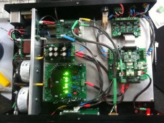
Here you can see the Arduino and CE-Designs shield (top center). Mounting in the front might have been more ideal if I had planned this from the beginning, but it still went in pretty clean and easy.
UserPostedImage

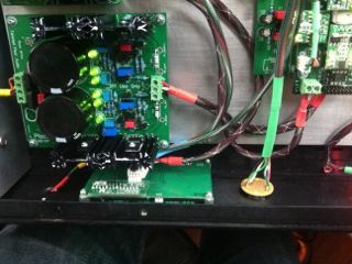
Below you can see the LCD panel mounted to the front. I started off with a negative backlight LCD and just this week upgraded to a Noritake VFD, which required a few changes. Mainly, I had to discretely supply power to the display since it draws something like 400mA, far more than Arduino can handle. I had to juggle things a bit to avoid adding more power supplies, so at the moment I've got 1/2 the LCDPS supplying the Buffalo, 1/2 supplying the Arduino and display and a tiny AMB labs 5v supply doing the Toslink. So far its working very well. LCDPS is certainly a nicer PS than Arduino requires, but this is what happens when a project evolves slowly over time. Since the VFD requires no BL (backlight connection) and is getting power straight from the supply, I'm really only using 2 pins from the Arduino + Shield to the display.
UserPostedImage

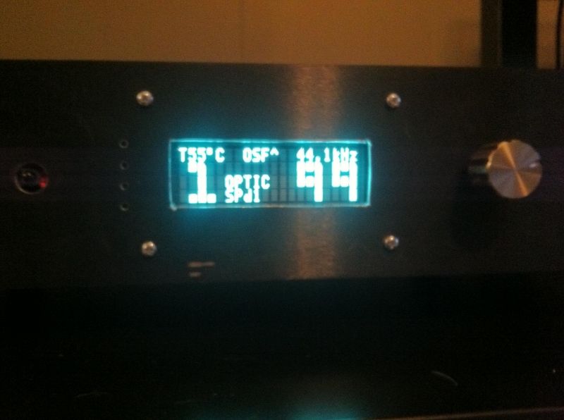
I found it pretty much impossible to get a realistic photo of the VFD, but here is something, for what its worth. Suffice to say I found it to be a huge improvement over the LCD. That said, its really bright, and as others have suggested I think it probably belongs behind some kind of smoked plexi.
UserPostedImage
UserPostedImage

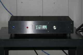
So all in all, its still hideous, but I'm holding off on a nice panel until I'm satisfied with the evolution. Honestly I like having ugly gear for a while, and its nice having a cheap stock front panel I can cut up to try things like this out.
UserPostedImage

Up next is the USB, I was about ready to go with an Amanero but its sounding like Russ is actually getting close to releasing, so I think I'll hold out a little longer. I guess when I do that, I'll add a 2nd USB port on the back for Arduino software updates.

Anyway, cheers to Corpius, GLT and everyone else with way more complex projects, I've stolen from you all and its been a lot of fun. BTW, its sounding killer and the functionality of controlling all the Sabre32 setting from my couch with a slick apple remote is pretty unbeatable.
gwikse  
#10 Posted : Monday, March 11, 2013 8:52:11 AM(UTC)
gwikse

Rank: Member

Groups: Member
Joined: 1/19/2011(UTC)
Posts: 332
Location: Oslo, Norway

Thanks: 14 times
Was thanked: 17 time(s) in 17 post(s)
Sweet system. Glad to see you got the VFD working. Can you adjust the contrast etc with that (as it seems your contrast level is a little high so that you see the screens nonactive squares)?

But yes, most VFD`s I`ve seen so far has been better with a smoked (or tinted rather) plate in front of it to dim the light a little. I believe noritake has some films for this on their site.
Corpius  
#11 Posted : Monday, March 11, 2013 5:23:05 PM(UTC)
Corpius

Rank: Member

Groups: Member
Joined: 2/1/2012(UTC)
Posts: 332
Location: The Netherlands

Thanks: 4 times
Was thanked: 18 time(s) in 18 post(s)
Nice project! Great work! Looks to that there still plenty of room for a USB input board. Are you using a soft start module or do my eyes deceive me?
Adastra  
#12 Posted : Wednesday, March 13, 2013 3:07:39 AM(UTC)
Adastra

Rank: Member

Groups: Member
Joined: 3/13/2012(UTC)
Posts: 22

Was thanked: 3 time(s) in 2 post(s)
Thanks fellas. There is no contrast adjustment for the VFD that I'm aware of, its definitely going to be tricky figuring out the right viewing angle and plexi treatment, but I'll admit I'm pretty tempted to start getting serious about a panel, if only because I'd hope any future add-ons would just change software, I'm definitely not looking for more knobs and switches.

Corpius, no soft-start, but a couple of AMB modules, one of the e24 power switch driver boards and one of the a25 linear PS boards, which is powering the toslink.
SCompRacer  
#13 Posted : Wednesday, March 13, 2013 4:45:40 PM(UTC)
SCompRacer

Rank: Member

Groups: Member
Joined: 1/6/2012(UTC)
Posts: 305
Location: Plainfield, IL

Thanks: 11 times
Was thanked: 26 time(s) in 21 post(s)
Nice work! This is what HiFi 2000/Modushop proposed for the bright displays when I was in planning stages.

Edited by user Wednesday, March 13, 2013 5:03:32 PM(UTC)  | Reason: Not specified

SCompRacer attached the following image(s):
plexyglass transparent o.JPG (124kb) downloaded 51 time(s).

You cannot view/download attachments. Try to login or register.
Adastra  
#14 Posted : Wednesday, March 20, 2013 11:24:08 PM(UTC)
Adastra

Rank: Member

Groups: Member
Joined: 3/13/2012(UTC)
Posts: 22

Was thanked: 3 time(s) in 2 post(s)
Rich, that looks great, just what I was picturing, thanks!
Sorry for the delay, I was enduring the misery that is South by Southwest. Now back to fun stuff!
Russ White  
#15 Posted : Wednesday, March 20, 2013 11:35:52 PM(UTC)
Russ White

Rank: Administration

Groups: Administration, Customer
Joined: 10/24/2006(UTC)
Posts: 3,979
Location: Nashville, TN

Thanks: 25 times
Was thanked: 89 time(s) in 83 post(s)
Looks great!
Rss Feed  Atom Feed
Users browsing this topic
GuestUser
Forum Jump  
You cannot post new topics in this forum.
You cannot reply to topics in this forum.
You cannot delete your posts in this forum.
You cannot edit your posts in this forum.
You cannot create polls in this forum.
You cannot vote in polls in this forum.