Rank: Member
Groups: Member
Joined: 8/20/2014(UTC) Posts: 43 
|
Hello, i have a BIIIse setup and i'm trying to use 2 OTTO II boards to switch between 2xI2S and 2xSPDIF inputs (using BIIIse IP_S switch too).
The problem is none of the 2 OTTO boards switches the signals: one of them simply doesn't switch (B1 is connected to A anything i do), the other just doesn't let any signal pass through (B1 or B2 are never connected to A anything i do).
Strangely, the 2 OTTO boards are wired just the same: 5.25Vdc to VCC, OE connected to GND, S connected to VCC via a 4.7K resistor, a switch between S and GND. Yet their behaviour is so different...
1st OTTO II board: switch open (S stays 5.25Vdc) -> B1 connected to A; switch closed (S goes to 0V) -> B1 still connected to A. B2 is never connected.
2nd OTTO II board: switch open (S stays 5.25Vdc) -> no signal passes; switch closed (S goes to 0V) -> no signal passes anyway and all A contacts go to GND.
Obviously all 4 signals go to BIIIse correctly if i connect them directly to BIIIse input connector one at a time, and they play flawlessly.
What did i wrong? Is my wiring uncorrect?
N.B. I live in Italy and we have 220V AC. Somewhere i read this could cause some issue on OTTO II, is it true?
Thanks in advance for your help!
|
|
|
|
|
|
Rank: Member
Groups: Member
Joined: 8/20/2014(UTC) Posts: 43
|
No help?
Yet it seems to me that many have problems switching OTTO boards, how could i solve them?
|
|
|
|
|
|
Rank: Administration
Groups: Administration, Customer
Joined: 10/24/2006(UTC)
Posts: 2,869
Location: Massachusetts, USA
Thanks: 2 times
Was thanked: 141 time(s) in 134 post(s)
|
220V makes no difference, unless you are applying that voltage to the board :)
You will need to post some pictures. It sounds like you have some wiring mixed up, or some bad solder joints.
|
|
|
|
|
|
Rank: Member
Groups: Member
Joined: 8/20/2014(UTC) Posts: 43
|
Originally Posted by: Brian Donegan  220V makes no difference, unless you are applying that voltage to the board :)
You will need to post some pictures. It sounds like you have some wiring mixed up, or some bad solder joints. I checked very well all solders and contacts. There was a bad connection on the second board (the one with all signals to gnd), i fixed and now both boards act just the same: they simply don't switch, A is always connected to B1... I took some measurements and found that vcc is 5.25V; S is 5.25V; gnd is 0 and so is OE. When i close the switch, S goes to gnd and is 0V, so it should switch and A should be connected to B2. But it doesn't: A is always connected to B1. Maybe the pull-up resistor value should be increased to 10k? Anyway, here is a pic of one of my boards: [img=http://postimg.org/image/484otbdqr/]Otto II[/img] You can see that OE is connected to gnd and S is connected to vcc using a 4.7k resistor. Green wire is 5.25Vdc, brown wire is gnd and red wire is S that goes to the switch. Edited by user Friday, March 20, 2015 11:25:24 PM(UTC)
| Reason: Not specified
|
|
|
|
|
|
Rank: Member
Groups: Member
Joined: 8/17/2010(UTC)
Posts: 368
Location: australia
Thanks: 8 times
Was thanked: 3 time(s) in 3 post(s)
|
Originally I did this and it worked: 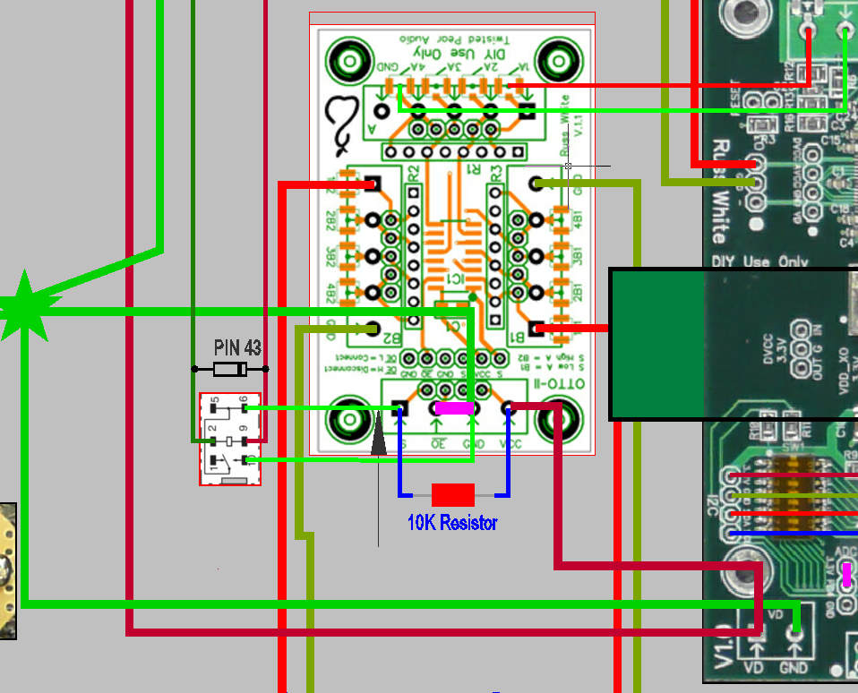 I'm now using a different setup as I am switching directly from the Arduino IO pin:
|
|
|
|
|
|
Rank: Member
Groups: Member
Joined: 8/20/2014(UTC) Posts: 43
|
Originally Posted by: DQ828
Originally I did this and it worked:
It looks just the same as my setup, except for the resistor (mine is 4.7K). Could that be the problem?
|
|
|
|
|
|
Rank: Member
Groups: Member
Joined: 8/17/2010(UTC)
Posts: 368
Location: australia
Thanks: 8 times
Was thanked: 3 time(s) in 3 post(s)
|
Originally Posted by: luca72c Originally Posted by: DQ828
Originally I did this and it worked:
It looks just the same as my setup, except for the resistor (mine is 4.7K). Could that be the problem? I doubt it but there only one way to find out :) Have you tried testing the OTTO with a multimeter to see if it is actually switching?
|
|
|
|
|
|
Rank: Member
Groups: Member
Joined: 8/20/2014(UTC) Posts: 43
|
Originally Posted by: DQ828
Have you tried testing the OTTO with a multimeter to see if it is actually switching?
I tried, but it doesn't...
|
|
|
|
|
|
Rank: Member
Groups: Member
Joined: 8/17/2010(UTC)
Posts: 368
Location: australia
Thanks: 8 times
Was thanked: 3 time(s) in 3 post(s)
|
Originally Posted by: luca72c Originally Posted by: DQ828
Have you tried testing the OTTO with a multimeter to see if it is actually switching?
I tried, but it doesn't... Good photos would help or at least couldn't hurt :)
|
|
|
|
|
|
Rank: Member
Groups: Member
Joined: 8/20/2014(UTC) Posts: 43
|
Originally Posted by: DQ828 Originally Posted by: luca72c Originally Posted by: DQ828
Have you tried testing the OTTO with a multimeter to see if it is actually switching?
I tried, but it doesn't... Good photos would help or at least couldn't hurt :) The one i linked is not enough? What should i show in other pics?
|
|
|
|
|
|
Rank: Member
Groups: Member
Joined: 6/17/2008(UTC) Posts: 921  Thanks: 1 times
Was thanked: 70 time(s) in 69 post(s)
|
Your link to the picture doesn't work avr300 attached the following image(s):  cut.jpg (18kb) downloaded 1 time(s).You cannot view/download attachments. Try to login or register.
|
|
|
|
|
|
Rank: Member
Groups: Member
Joined: 8/20/2014(UTC) Posts: 43
|
|
|
|
|
|
|
Rank: Member
Groups: Member
Joined: 8/17/2010(UTC)
Posts: 368
Location: australia
Thanks: 8 times
Was thanked: 3 time(s) in 3 post(s)
|
Originally Posted by: luca72c It looks like the green wire is VCC so it should be going to the power supply & your brown wire is going to ground and the red wire is going to S which means red & brown wires should be going to the switch. Is that whats happening? The brown wire should also be going to the star ground or the power ground. Edited by user Monday, March 23, 2015 9:15:10 AM(UTC)
| Reason: Not specified
|
|
|
|
|
|
Rank: Member
Groups: Member
Joined: 8/20/2014(UTC) Posts: 43
|
Originally Posted by: DQ828 Originally Posted by: luca72c It looks like the green wire is VCC so it should be going to the power supply & your brown wire is going to ground and the red wire is going to S which means red & brown wires should be going to the switch. Is that whats happening? The brown wire should also be going to the star ground or the power ground. Sharp eye, my friend! I connected the second (normally closed) wire from the switch directly to the power ground, without passing via OTTO II's ground connector. This way S goes to ground when the switch is closed, as stated in the Integration Guide. I have to connect it to OTTO II's ground connector, instead? Doesn't it go to power ground anyway?
|
|
|
|
|
|
Rank: Member
Groups: Member
Joined: 8/17/2010(UTC)
Posts: 368
Location: australia
Thanks: 8 times
Was thanked: 3 time(s) in 3 post(s)
|
I am no expert but I have had some weird things happen with grounding so I can only suggest you connect the switch to the otto ground and see what happens
|
|
|
|
|
|
Rank: Administration
Groups: Administration, Customer
Joined: 10/24/2006(UTC)
Posts: 2,869
Location: Massachusetts, USA
Thanks: 2 times
Was thanked: 141 time(s) in 134 post(s)
|
Originally Posted by: luca72c
Sharp eye, my friend!
I connected the second (normally closed) wire from the switch directly to the power ground, without passing via OTTO II's ground connector. This way S goes to ground when the switch is closed, as stated in the Integration Guide.
I have to connect it to OTTO II's ground connector, instead? Doesn't it go to power ground anyway?
What you have will work, as long as those two ground are indeed connected somewhere. I also need to point out that you cannot test operation of the OTTO with just a multi-meter conductivity test. You need to use a ground-biased signal (signal + ground) with the signal ground attached to the signal ground pads. For simple testing, use a AA battery as your signal (+ terminal to A or B pad, - to signal GND pad) and check for voltage at the output when switched. Edited by user Monday, March 23, 2015 1:14:11 PM(UTC)
| Reason: Not specified
|
|
|
|
|
|
Rank: Member
Groups: Member
Joined: 8/20/2014(UTC) Posts: 43
|
Originally Posted by: Brian Donegan
What you have will work, as long as those two ground are indeed connected somewhere.
I also need to point out that you cannot test operation of the OTTO with just a multi-meter conductivity test. You need to use a ground-biased signal (signal + ground) with the signal ground attached to the signal ground pads. For simple testing, use a AA battery as your signal (+ terminal to A or B pad, - to signal GND pad) and check for voltage at the output when switched.
Thank you for clarifying about that. The 2 grounds are connected at power ground star, that leads to Placid HD ground (connected to the star are the 2 OTTO II boards, a TOSLINK small board and of course BIIIse). I tested the boards using real PCM/SPDIF signals and sending signals to Buffalo III, but they don't work in the setup i pictured in the photo. The only remaining thing to check is using a 10K resistor instead of 4.7K. I'll check as soon as i can.
|
|
|
|
|
|
Rank: Administration
Groups: Administration, Customer
Joined: 10/24/2006(UTC)
Posts: 2,869
Location: Massachusetts, USA
Thanks: 2 times
Was thanked: 141 time(s) in 134 post(s)
|
As long as the I2S and S/PDIF signal grounds were connected to the GND connections, that should be a good test.
|
|
|
|
|
|
Rank: Member
Groups: Member
Joined: 8/20/2014(UTC) Posts: 43
|
Hello,
just to confirm (sorry for the delay) that using a 10k resistor, one of the 2 OTTO boards started working good (the one switching I2S signals).
The other board had a tiny solder problem below a connector (these circular pads are really too small for me!) and by fixing that, the issue was solved.
Thank you very much to everybody!
|
|
|
|
|
|
Forum Jump
You cannot post new topics in this forum.
You cannot reply to topics in this forum.
You cannot delete your posts in this forum.
You cannot edit your posts in this forum.
You cannot create polls in this forum.
You cannot vote in polls in this forum.

