Twisted Pear Audio Support
»
User Galleries
»
Project Gallery
»
Buffalo III *now* Dual Mono Build / Denon DVD-3910 Mod
Rank: Member
Groups: Member
Joined: 8/17/2010(UTC)
Posts: 368
Location: australia
Thanks: 8 times
Was thanked: 3 time(s) in 3 post(s)
|
Originally Posted by: SCompRacer  Modushop sent me a progress report, off to anodizing! Should ship next week. Very nice, can I ask how much something like that costs?
|
|
|
|
|
|
Rank: Member
Groups: Member
Joined: 2/1/2012(UTC)
Posts: 332
Location: The Netherlands
Thanks: 4 times
Was thanked: 18 time(s) in 18 post(s)
|
Originally Posted by: SCompRacer Modushop sent me a progress report, off to anodizing! Should ship next week. Looks great Rich! With such an front plate, lots of transformers and all other stuff it will become a heavy beast! |
|
|
|
|
|
|
Rank: Member
Groups: Member
Joined: 1/6/2012(UTC)
Posts: 305
Location: Plainfield, IL
Thanks: 11 times
Was thanked: 26 time(s) in 21 post(s)
|
Thanks for the kind words. I’m not much of a designer like gwikse or Corpius, but it kind of suits me. Plain but hard working…;) It will be heavy for sure...but won't be flexing when I pick it up like it does with the friendly case. I have no problem disclosing the cost as modushop's prices are posted for each service, and I won’t make you look it up. I am not at home, but recall it being ~ 235 Euro, which is $300 US including shipping. PESANTE 3U 10mm panel, 450mm x 430mm x 120mm. Add ons were both sides machined, anodize after machine, drilled inner base, 29mm shiny knob, fully vented top cover and four of their anti vibration feet. I added a cavity in rear of panel to move the LCD closer to the face of front panel. Andrea also drilled and tapped for the LCD mounting holes. No ink fill as they only use black ink, not much use on a black face plate. We shall see how I do with the paint fill of lettering/TP logo. Initially it seemed like too much to spend for an enclosure, but considering the investment in the DAC it really isn’t. Edited by user Wednesday, November 21, 2012 9:42:00 PM(UTC)
| Reason: Not specified |
|
|
|
|
|
|
Rank: Administration
Groups: Administration, Customer
Joined: 10/24/2006(UTC)
Posts: 3,979
Location: Nashville, TN
Thanks: 25 times
Was thanked: 89 time(s) in 83 post(s)
|
Great work! I really enjoyed reading about your DAC. Thanks for sharing, and thank you for your kind words.
|
|
|
|
|
|
Rank: Member
Groups: Member
Joined: 1/6/2012(UTC)
Posts: 305
Location: Plainfield, IL
Thanks: 11 times
Was thanked: 26 time(s) in 21 post(s)
|
Thanks Russ! You guys earn the praise. My enclosure arrived from Modushop! It took a week instead of weeks like I thought. 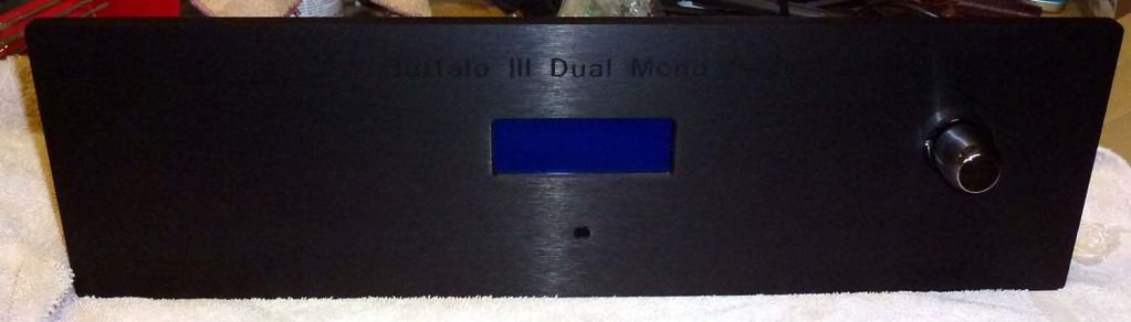 The LCD dropped right in, fit perfectly. I had a rear cavity machined in front panel so the LCD screen is close to the face. There is also a chamfer around the opening. The cavity above the LCD rectangle is for the I2C LCDextra IO board that Corpius put me on to. (Thanks Corpius for all the help!) It didn't need to be that deep but allows plenty of clearance now. The IO board is soldered to the LCD header. The LCD screw retaining holes were perfectly drilled and tapped by modushop. If only I could do that good mounting the Arduino board. More to come, lots to do! I was thinking of eliminating one PS. Currently using the + side of an LCBPS for the Arduino and a 1/2 of an LCDPS for my Sidecar/ Teleporter module (9v transformer on LCDPS). If I use a 15v transformer on my LCDPS, I'll get the voltage I need for the Arduino/LCD. Will I still be able to adjust the other side of LCDPS down to 5 volts for the Sidecar/Teleporter and future USB module using a 15v tranny? Edited by user Thursday, December 6, 2012 5:28:37 PM(UTC)
| Reason: Not specified SCompRacer attached the following image(s):  pesante_1.jpg (177kb) downloaded 22 time(s). pesante_2.jpg (131kb) downloaded 37 time(s). pesante_3.jpg (53kb) downloaded 42 time(s). pesante_4.jpg (101kb) downloaded 65 time(s). pesante_5.jpg (167kb) downloaded 62 time(s).You cannot view/download attachments. Try to login or register. |
|
|
|
|
|
|
Rank: Member
Groups: Member
Joined: 1/19/2011(UTC)
Posts: 332
Location: Oslo, Norway
Thanks: 14 times
Was thanked: 17 time(s) in 17 post(s)
|
Looks great  Hard to see the TPA logo on those images though. I use a LCDPS with 9V transformer (measured higher though) to supply 5.25V to dac and sidecar, etc and 7,5V to the arduino and lcd from the other side. Has been running like that now for ages with no hickups.
|
|
|
|
|
|
Rank: Member
Groups: Member
Joined: 2/1/2012(UTC)
Posts: 332
Location: The Netherlands
Thanks: 4 times
Was thanked: 18 time(s) in 18 post(s)
|
Looks great Rich! Are you going to fill the engravings? If yes, which color? Ik read your post earlier this morning on my tablet pc. For some reason the images are not shown when I use this. I'll try to get my front plate done soon. The guy from the workshop at my work is back from his holiday, so I hope he has dome time for me soon. . Edited by user Thursday, December 6, 2012 10:52:44 AM(UTC)
| Reason: Not specified |
|
|
|
|
|
|
Rank: Member
Groups: Member
Joined: 1/6/2012(UTC)
Posts: 305
Location: Plainfield, IL
Thanks: 11 times
Was thanked: 26 time(s) in 21 post(s)
|
Thanks! Black is tough to shoot but this one shows the logo a bit better. This was taken during the unwrap. That is cardboard/paper dust that shows up as mars on the panel. After a wipe the front panel has no imperfections. I may have to go with a green or black LCD also. Since I am partially color blind the wife says she will pick out the right shade of green for the lettering/logo fill. Or an antique gold. I had the Arduino connected to my LCDPS at one time and the most I could get out of it was 6.5v, then the voltage dropped like I ran off the pot windings. It worked but display got brighter with 12v. I'll try the other side of LCDPS when it breathes again. Oh, some good news that saves some work, the modushop knob slid right on the .25" partial flat Panasonic rotary encoder shaft. The knob also has an Allen screw which I don't think they mention or show. IIRC they just say "6mm with serration grain." The Allen screw snugs up on the partial flat of the encoder shaft and turns concentric, so no rubbing of the flange in the panel cavity occurs. Edited by user Thursday, December 6, 2012 5:04:47 PM(UTC)
| Reason: Not specified SCompRacer attached the following image(s): tplogo.jpg (124kb) downloaded 44 time(s).You cannot view/download attachments. Try to login or register. |
|
|
|
|
|
|
Rank: Member
Groups: Member
Joined: 1/6/2012(UTC)
Posts: 305
Location: Plainfield, IL
Thanks: 11 times
Was thanked: 26 time(s) in 21 post(s)
|
I am happy to say I am mostly finished with my dual mono build! I had to take an existing light picture of the front panel in an attempt to show what it looks like in real life. The flash tends to really lighten the color fill in the front panel engraving. I am waiting for an Amanero USB/I2S module, and Digi Key mis-packaged the incorrect value resistors for the AES/EBU input. The USB input is just a hole stuffer for now. I plan to redo the rear panel labeling when I install the USB module. I am thinking up high near the Teleporter to keep the I2S wires short. An OTTO II for switching could be added. I tried to think modular in that the rear panel, front panel and toroidal farm can be removed if the need arises. Edited by user Sunday, December 16, 2012 11:15:11 PM(UTC)
| Reason: Not specified SCompRacer attached the following image(s): pesante_0.jpg (55kb) downloaded 150 time(s). pesante_13.jpg (234kb) downloaded 247 time(s). pesante_14.jpg (206kb) downloaded 200 time(s). pesante_12.jpg (85kb) downloaded 164 time(s).You cannot view/download attachments. Try to login or register. |
|
|
|
|
|
|
Rank: Member
Groups: Member
Joined: 1/6/2012(UTC)
Posts: 305
Location: Plainfield, IL
Thanks: 11 times
Was thanked: 26 time(s) in 21 post(s)
|
Some build pics. I drilled and tapped holes to mount the Arduino board (pictured with Corpius's shield) and IR receiver board. I also drilled a cavity for the IR receiver to get it closer to the face of front panel and give me off axis control. Somehow I removed that cavity during changes made to the design in front panel express. It would have been nice to have all that work done by the CNC machine. I am glad I went with the Hi Fi 2000 drilled base option. It made assembly easy and stiffened up the chassis. After getting the components positioned and wired, I added the walls of the enclosure. My toroidal farm wouldn’t do well installed on just the lower panel. At least two holes of every board lined up with pre-drilled holes in base. Andrea at Modushop was very helpful and nice to deal with while I was finalizing the front panel machining. Due to my inside out assembly procedure and the toroidal farm blocking access, I stud mounted the front panel. There is just enough room to swing a small box-open end wrench to tighten the nuts, although getting a washer and nut on is tricky. A short USB cable is connected to a Neutrik D panel USB connector at right side of enclosure so the Arduino can be programmed without removing the cover. EDIT: You might notice two holes drilled in the rotary encoder knob cavity. This was a last minute addition for a future project. I'll add LED's for the lock and mute behind the knob like I saw some folks do here. I'll get a different color for mute and use my original green one for the lock. Edited by user Sunday, December 16, 2012 11:08:54 PM(UTC)
| Reason: Not specified SCompRacer attached the following image(s): pesante_5.jpg (38kb) downloaded 49 time(s). pesante_6.jpg (66kb) downloaded 55 time(s). pesante_9.jpg (218kb) downloaded 114 time(s). pesante_15.jpg (87kb) downloaded 91 time(s).You cannot view/download attachments. Try to login or register. |
|
|
|
|
|
|
Rank: Member
Groups: Member
Joined: 1/6/2012(UTC)
Posts: 305
Location: Plainfield, IL
Thanks: 11 times
Was thanked: 26 time(s) in 21 post(s)
|
The Testors paint fill of the front panel went well. It is very hard to stay "in the lines" with the color fill even with a tiny artists brush. I found a new bondo spreader used as a squeegee moved most of the excess paint to an area where it could be wiped off the panel without removing paint from the engraved areas. After allowing the color to set a few minutes, I used cotton swaps moistened with thinner to get excess paint off. It leaves a film that can be easily removed once the paint dries. I followed up with an old dish towel wrapped tightly around the spreader moistened with thinner. It was a smooth tightly woven towel (not fuzzy). The plastic spreader did no harm to the front panel. The toroidal farm mount is thick 1/4" (6.35mm) aluminum. I drilled and tapped threads in the mount to make it easy to install to the base. I couldn't locate any rubber grommets for that thickness material to insulate the wire pass through holes. A trip to the local Ace Hardware for some metric screws got me looking thought their hardware offerings and I found some snap in plastic bushings. They had an assortment of small to larger sizes. I used 3/8" (9.5mm) for the secondary wiring and 1/2" (12.7mm) for the mains power. They were 3/8" (9.5mm) long so they extend through the thick transformer bracket. Some folks have asked me why so many toroidals. Well I had the Twisted Pear LCDPS and LCDPS linear power supplies from early testing with the single BIII build. (Sounded better to me with the shunting power supplies). I used the + side of the LCBPS to power the Arduino/LCD. One side of the LCDPS powers the Sidecar/4 channel input board and the other side powers Teleporter and future USB module. I could lose one 9v tranny and split the secondaries on the remaining one to power the two Placid HD's, but then I lose galvanic isolaton. It was so quiet even with the rats nest wiring in the friendly case that I did not want to risk possibly adding any. This was the first time I had two inputs connected to the 4 channel input board (nothing was connected to the second input). I was getting dropouts where I never had them before (In my best Mr. Bill Oh...! Nooooo!) until I lowered the Sidecar/input board power to 4.75v. Edited by user Sunday, December 16, 2012 11:34:43 PM(UTC)
| Reason: Not specified SCompRacer attached the following image(s): pesante_10.jpg (56kb) downloaded 138 time(s). pesante_8.jpg (196kb) downloaded 84 time(s). pesante_7.jpg (232kb) downloaded 110 time(s).You cannot view/download attachments. Try to login or register. |
|
|
|
|
|
|
Rank: Member
Groups: Member
Joined: 1/19/2011(UTC)
Posts: 332
Location: Oslo, Norway
Thanks: 14 times
Was thanked: 17 time(s) in 17 post(s)
|
Very nice You should replace the lcd at some point though ;) Based on what I see on the images, I can easily see the Oled I am using raising the looks even further. Btw: Is that a Pesante chassis? I was wondering how that looked compared to the slimline rack solutions. I like the cleaner look of Pesante (the side-panel USB solution would be hard with the Slimline as well). Edited by user Monday, December 17, 2012 12:05:50 AM(UTC)
| Reason: Not specified
|
|
|
|
|
|
Rank: Member
Groups: Member
Joined: 1/6/2012(UTC)
Posts: 305
Location: Plainfield, IL
Thanks: 11 times
Was thanked: 26 time(s) in 21 post(s)
|
Thanks gwiske. Yes, a green something will be in my future.....but.... right now...... right now......right now, its time to kick out the jams m#########! ;) (Tell me where I heard that and I'll be surprised!) It don't look bad enough to keep me from using it.  Yes, it is a Pesante 3U, 10mm panel, 450mm x 430mm x 120mm. And I am glad I didn't go with a smaller enclosure. Quiet, no hums, loving it. Now I have a cover and can leave it upstairs and not worry about our cat doing mods on it. I sourced some longer flat head screws that attach the drilled base to the side panels. I added washers under the nuts as the slots in the drilled base are near as wide as the nuts. I also sourced nylon lock nuts so it doesn't loosen up with the pounding bass. EDIT: OK, this green on black LCD screen is ordered. Thanks for the link Corpius. Zcw~~_12.JPG) Edited by user Monday, December 17, 2012 9:16:34 PM(UTC)
| Reason: Not specified |
|
|
|
|
|
|
Rank: Member
Groups: Member
Joined: 2/1/2012(UTC)
Posts: 332
Location: The Netherlands
Thanks: 4 times
Was thanked: 18 time(s) in 18 post(s)
|
|
|
|
|
|
|
|
Rank: Member
Groups: Member
Joined: 1/6/2012(UTC)
Posts: 305
Location: Plainfield, IL
Thanks: 11 times
Was thanked: 26 time(s) in 21 post(s)
|
OK, here you go, with the green on black screen. 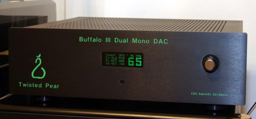 Edited by user Saturday, December 29, 2012 10:56:04 PM(UTC)
| Reason: Not specified SCompRacer attached the following image(s): pesante_0a.jpg (63kb) downloaded 63 time(s).You cannot view/download attachments. Try to login or register. |
|
|
|
|
|
|
Rank: Member
Groups: Member
Joined: 1/19/2011(UTC)
Posts: 332
Location: Oslo, Norway
Thanks: 14 times
Was thanked: 17 time(s) in 17 post(s)
|
Sweeeet
|
|
|
|
|
|
Rank: Administration
Groups: Administration, Customer
Joined: 10/24/2006(UTC)
Posts: 3,979
Location: Nashville, TN
Thanks: 25 times
Was thanked: 89 time(s) in 83 post(s)
|
|
|
|
|
|
|
Rank: Member
Groups: Member
Joined: 2/1/2012(UTC)
Posts: 332
Location: The Netherlands
Thanks: 4 times
Was thanked: 18 time(s) in 18 post(s)
|
That really finished it. Looks great Rich! |
|
|
|
|
|
|
Rank: Member
Groups: Member
Joined: 8/17/2010(UTC)
Posts: 368
Location: australia
Thanks: 8 times
Was thanked: 3 time(s) in 3 post(s)
|
|
|
|
|
|
|
Rank: Member
Groups: Member
Joined: 1/6/2012(UTC)
Posts: 305
Location: Plainfield, IL
Thanks: 11 times
Was thanked: 26 time(s) in 21 post(s)
|
Thanks for the kind words! I got the Amanero USB to I2S module installed and it sounds great! No noise when connected to my laptop. I'm not sure if this is the last USB module I'll use so I opted for internal mounting, using a short USB patch cord from a panel mount Neutrik USB connector. I snipped the power wire in my short USB patch cord; power is supplied by 1/2 of an LCDPS set to 3.3v. I am also on the GB list for the Acko isolator/reclock board. I used small coax to connect the I2S signals. The coax braid is used as ground at both ends. I cut some old good quality S Video cables up to get the coax. Some cheaper S Video I had used a shield wrapped over wires. A ribbon cable would have worked too, leaving a GND cable between each signal line, but I find the small coax easier to work with. Edited by user Monday, January 14, 2013 9:56:45 PM(UTC)
| Reason: Not specified SCompRacer attached the following image(s): amanero_usb_2.jpg (206kb) downloaded 108 time(s). amanero_usb_3.jpg (236kb) downloaded 77 time(s).You cannot view/download attachments. Try to login or register. |
|
|
|
|
|
|
Twisted Pear Audio Support
»
User Galleries
»
Project Gallery
»
Buffalo III *now* Dual Mono Build / Denon DVD-3910 Mod
Forum Jump
You cannot post new topics in this forum.
You cannot reply to topics in this forum.
You cannot delete your posts in this forum.
You cannot edit your posts in this forum.
You cannot create polls in this forum.
You cannot vote in polls in this forum.

