Buffalo III Build in a Low Profile EnclosureI recently completed my Buffalo III. I thought it would be a good idea to show others who are contemplating this project how I approached the build in general, especially with regard to fitting it into a low profile enclosure.
And for any Twisted Pear first-timers thinking of ordering and building the Buffalo III kit, I hope this post gives you some extra encouragement to move forward. It really is a lot of fun and very rewarding; and the sound is amazing! It is not a beginner’s project, but I believe that anyone with just a moderate amount of DIY electronic experience could complete it. There is a lot of help available. Reading and understanding the
Buffalo III DAC Integration Guide is essential, and browsing through the entire diyAudio thread
Buffalo III – flexibility without compromise and the relevant Twisted Pear support forums is highly recommended.
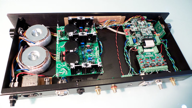
THE BUILDMy Buffalo III is comprised of the Placid HD and Placid HD BP with matching transformers, the Legato 3.1, the Buffalo III DAC, the Sidecar, the 4-channel S/PDIF module, the 4 input selection switch, and the Toslink receiver module.
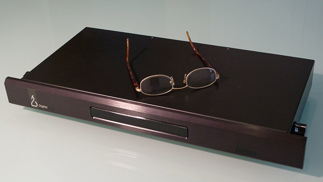
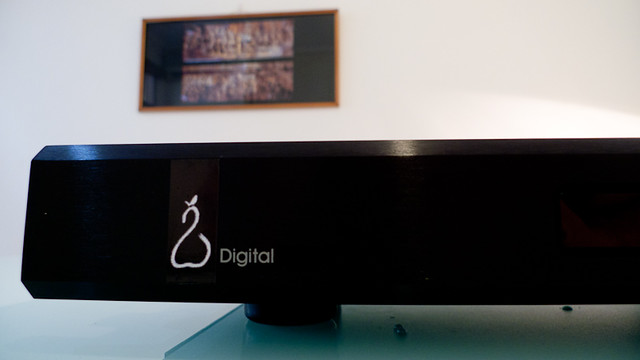
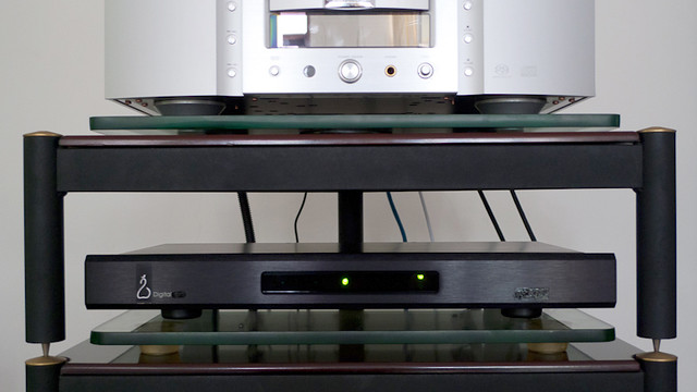
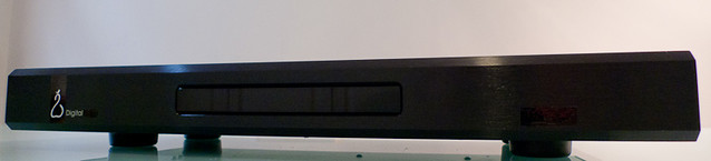
The EnclosureI had an old Genesis Digital Lens unit gathering dust in a cabinet. It seemed to be a perfect enclosure for the BIII if I could fit everything in and manage the heat. It has beautiful faceplate with a transparent window.
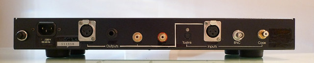
The set of socket holes on the back panel closely matched what I needed for my Buffalo III build.
I painted black over the labeling I did not want, including the ‘Lens’ on the faceplate so that it now simply says ‘Digital’. I made a Twisted Pear logo for the front which is printed on black adhesive vinyl.
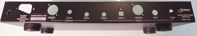
The back panel, after minor modifications, now offers from left to right: power switch, IEC power in, right balanced out, headphone out, right single-ended out, left single-ended out, Toslink in, left balanced out, BNC in, and coax in. Not the perfect arrangement, but pretty good considering it is an adapted enclosure. (Note that the balanced output sockets are reversed gender from what one would normally see; this to fit my home-brew balanced cables.)
 Layout
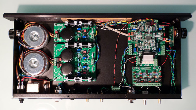
I wanted to separate as much as possible the digital/analogue sections from the power supply. I also wanted to minimize the distance from the S/PDIF-4 board inputs to their respective input sockets. Finally, I wanted to avoid signal wires crossing or passing near to the power and control wiring. The layout that I came up with achieves these goals.
 Tight Fit Front to Back
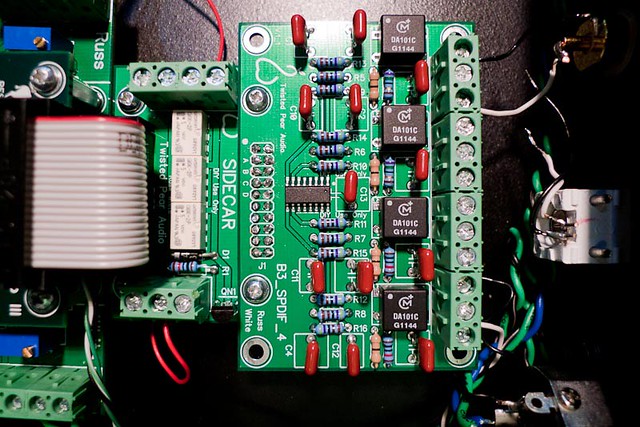
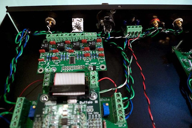
In order fit things in I had to find a way to reduce the length of the Buffalo/Legato – Sidecar – S/PDIF-4 chain. I wanted to keep these in a straight line with the inputs close to the back. But mounting each of the modules separately would have squeezed the S/PDIF-4 inputs up too close to the back panel. The solution was to hard-wire the Sidecar and the S/PDIF-4 together as a combined module. The connector holes are lined up over each other and short wires are soldered through the holes to make the connections.
 Tight Fit Vertically and Heat Dissipation
 I had to slightly reduce the length of the vertical stacking connectors between the Legato and the BIII boards, so that the AVSS on top of the BIII had some breathing room – not too close to the enclosure lid.
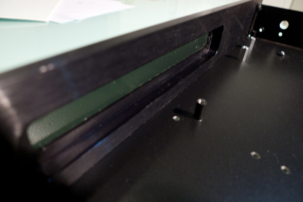
The other issue to deal with was the height of the Placid heat sinks – they were too high with the supplied mounting hardware. I used nuts as spacers under the Placid boards to lower them so that the heat sinks would not exceed the internal height of the enclosure. As the enclosure was small, providing only minimal ventilation, I decided to use the top of the enclosure as a heat sink. The height of the Placid boards is adjusted so that the lid of the enclosure very lightly and firmly presses against the tops of the heat sinks. I have applied thermal compound on the top of each heat sink to maximize the thermal transfer.
Here you can see where contact has been made on the inside of the enclosure lid.
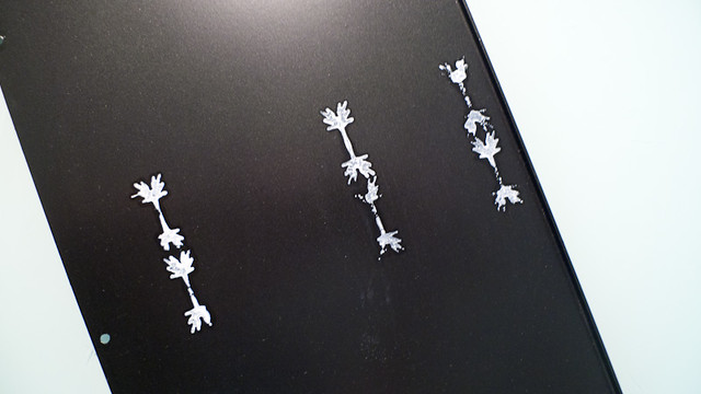
After a couple of hours of operation the lid directly over the Placids gets quite hot. This is a good thing! The far left and right sides of the lid remain moderately warm.
Buffalo III ‘Wing’ ControlsOne issue I had was how to deal with the needed controls for switching and volume as there was no room on the back panel and the front faceplate was thick and heavy and I didn’t have the tools to drill into that. Anyway, the faceplate is beautiful, and would have been ruined with knobs protruding up front. So, I decided to place the controls and their knobs on the sides of the enclosure, tucked right up against the faceplate wings that extend to the left and right. Input switching is on the left side and the volume control is on the right.
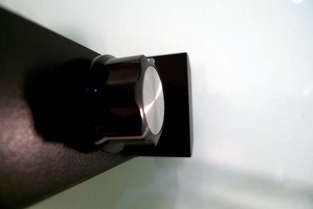
Despite the odd visual impact, it is amazing how well this works as the knobs are essentially out of sight but easy to reach and manipulate.
Display WindowOne cool advantage of using the old Digital Lens enclosure is the opportunity to use the long horizontal window in the faceplate to show the selection LEDs and the mute/lock LEDs. The selection LEDs are spread evenly across most of the window so it is easy to see which input is selected. The mute and lock are tucked in on the right side of the window.
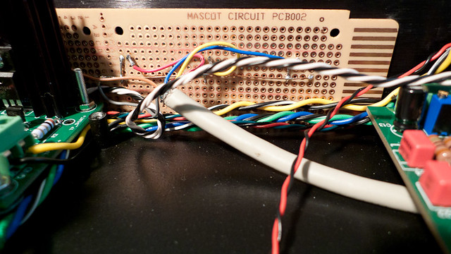
The LEDs are held in place in the display window on a piece of perfboard. The big gray multi-strand cable comes from the switch and provides leads to each of the LEDs. This homebrew monstrosity looks crude alongside the beautiful green TP boards, but it works.
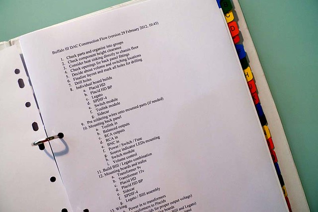
 THE PROCESS
Constructing the BIII took me about 10 days – two weekends and the evenings of the intervening work week. While waiting for the kit to arrive I spent a lot of time reading through the support forums and the integration guide. It was important for me to get organized ahead of time and to visualize every step of the build. I used a notebook to compile notes from the integration guide and the forums, and drafted a construction flow outline to keep things orderly.
Frankly, the assembly of the Twisted Pear kits was easy. The location of each part is marked clearly on the circuit boards and parts are neatly labeled in tiny plastic bags. It is basically a paint-by-number task. Take care to mount and solder each part correctly and, when in doubt, be sure to refer to the
Building Your First Module in the Twisted Pear document repository.
Getting the enclosure and fittings ready took the greatest amount of time and effort.
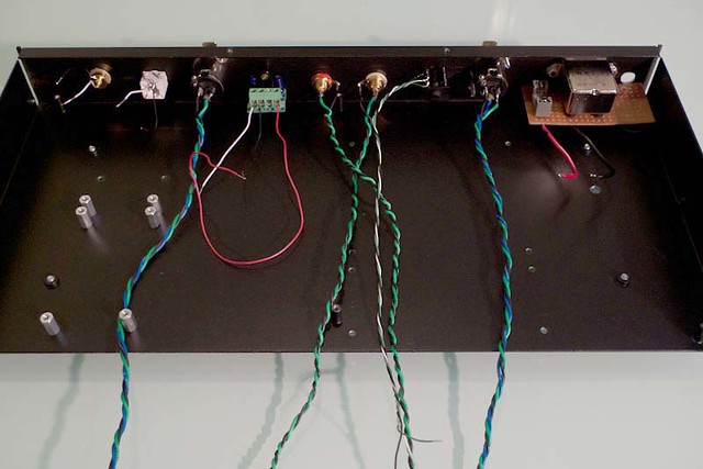
There is a lot of connection cabling to hook up to get everything linked, and this takes time. Be sure that all stranded wires are pre-tinned with solder.
A particularly challenging part of the build for me was working with the ribbon cable and connectors, as I had never worked with these before. Also, the SMD jumper soldering on the bottom of the BIII board was a challenge, again first time for me.
TroubleshootingNo matter how much you plan, you cannot anticipate your own errors. On the Tridents I mistakenly installed resistors at the R4 locations, even though there were SMD resistors there already in place! In addition, I had trouble attaining a stable lock on my Toslink input through the 4-channel S/PDIF level converter module. I was able to find the solutions on the support forum.
Thanks to the Twisted Pear TeamThe success of my build can be directly attributed to the flexible integration options that are available when combining the various TP modules. Thank you to Russ White and Brian Donegan for designing the modules in this way, and to Leon van Bommel for describing it all so clearly.
- Steve

