Rank: Member
Groups: Member
Joined: 8/17/2011(UTC)
Posts: 12
Location: abu dhabi
|
Howdey Gents, I am a bit of a newbie hence my question, which is: When building the new 4 input source selector for the Buffalo III there are resistors options for TTL or ABSU, where do these go? as the PCB is already populated fully. Can a diagram be supplied ref all this (also to include the rotary switch PCB options for illuminating the LEDS as I have read it- but don’t fully understand it as yet (and can’t proceed till I do !)  cheers Johnny
|
|
|
|
|
|
Rank: Administration
Groups: Administration, Customer
Joined: 10/24/2006(UTC)
Posts: 2,869
Location: Massachusetts, USA
Thanks: 2 times
Was thanked: 141 time(s) in 134 post(s)
|
R1-R4 on the S/PDIF4 board are the termination resistors for the inputs. The kit now comes with three sets of resistors for these positions: 75R for consumer-level S/PDIF (standard), 110R for AES/EBU, and 10K for TTL-level S/PDIF. Basically, use the correct termination resistor for each position, depending on which type of input you want it to accept. The switch board connects to positions 1-4 of the I/O header on the Buffalo-III. Use the same four positions on the switch board (observe the orientation marks). The correct four positions on the switch board actually have a box drawn around them in the silk. (SEE FIRST PICTURE) The LEDs can either be mounted directly on the switch board, or remotely. Mounting on the switch board allows you to have them right next to your source-selection knob on your front panel. Remote mounting let's you put them anywhere you want. No additional wiring is required for the LEDs. Edited by user Friday, November 11, 2011 5:42:18 AM(UTC)
| Reason: Not specified Brian Donegan attached the following image(s):  switch_board_orientation.JPG (165kb) downloaded 1,034 time(s). standard_led.JPG (121kb) downloaded 1,023 time(s).You cannot view/download attachments. Try to login or register.
|
|
|
|
|
|
Rank: Member
Groups: Member
Joined: 8/17/2011(UTC)
Posts: 12
Location: abu dhabi
|
Thank you Brian, wonderfully explaned, with great pictures.
Ever thought of a "Dummys Guide" for the rest of us (who aint that tecnical/perhaps shouldent be doing thsi alone?)-- However you have to cut your teeth on something.
Best regards and much thanks
Johnny
|
|
|
|
|
|
Rank: Member
Groups: Member
Joined: 8/23/2011(UTC)
Posts: 17
Location: Europe/Germany
|
Thank you for this wonderful explanation! I've a question referring to the "Buffalo III DAC Integration Guide" on side 12: Quote:Tip: If you don’t use all 4 inputs of the S/PDIF-4 Input Board, you could
just use the standard 4 position switch, and use one of the positions to
switch the Sidecar module. Which preconditions does this have? Is it enough not to connect a input on the green terminals on the Input Board, or do I have to leave the resistor open, or do I only need to connect the 2 correct pins from the 2bit-selector-board with the "trigger" terminal on the sidecar board? Thank you very much! Kind regards Matthias
|
|
|
|
|
|
Rank: Member
Groups: Member
Joined: 8/23/2011(UTC)
Posts: 17
Location: Europe/Germany
|
Hi,
it would be nice if anybody could help me.
Kind regards,
Matthias
|
|
|
|
|
|
Rank: Administration
Groups: Administration, Customer
Joined: 10/24/2006(UTC)
Posts: 3,979
Location: Nashville, TN
Thanks: 25 times
Was thanked: 89 time(s) in 83 post(s)
|
Hmm, what I would do if you want to use one position to switch the side car is simply run a wire from that position's remote LED spot to the "B" (base) terminal on the sidecar. You can even leave the LED in place.
Give it a try.
|
|
|
|
|
|
Rank: Member
Groups: Member
Joined: 8/23/2011(UTC)
Posts: 17
Location: Europe/Germany
|
Thanks a lot, Russ, i'll try that!
|
|
|
|
|
|
Rank: Member
Groups: Member
Joined: 8/23/2011(UTC)
Posts: 17
Location: Europe/Germany
|
Hi!
If i turn the switch, then a relais is clicking, so i think it works. To be totaly sure, i would need the tpa usb transport! ;)
My buffalo sings, i like it! Now i'm unpatiently waiting for the new high-res transport! (i don't ask when the transport is ready)
Kind regards
Matthias
|
|
|
|
|
|
Rank: Member
Groups: Member
Joined: 1/6/2012(UTC)
Posts: 305
Location: Plainfield, IL
Thanks: 11 times
Was thanked: 26 time(s) in 21 post(s)
|
I have my Sidecar wired as described. Number 4 of the remote LED terminals (numbered 1-4) from the selector switch to the Sidecar Base terminal. I hear a soft click but don't get any DSD/PCM signal through the Sidecar relays to the B III board. I get 1.9 V at any of the LED remote header pins (1-4) individually when selected. If I apply higher voltage to the Base terminal (5 volts), I get the signal through the Sidecar relays to the B III inputs. I am able to select any of the remaining three inputs connected to my S/PDIF 4 input board with the Sidecar in place. R1 on the Sidecar measures 9.98K Ohms. 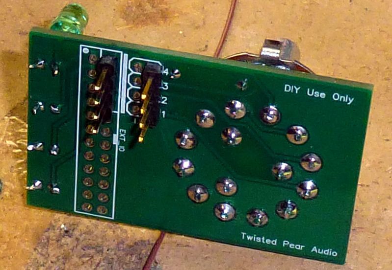 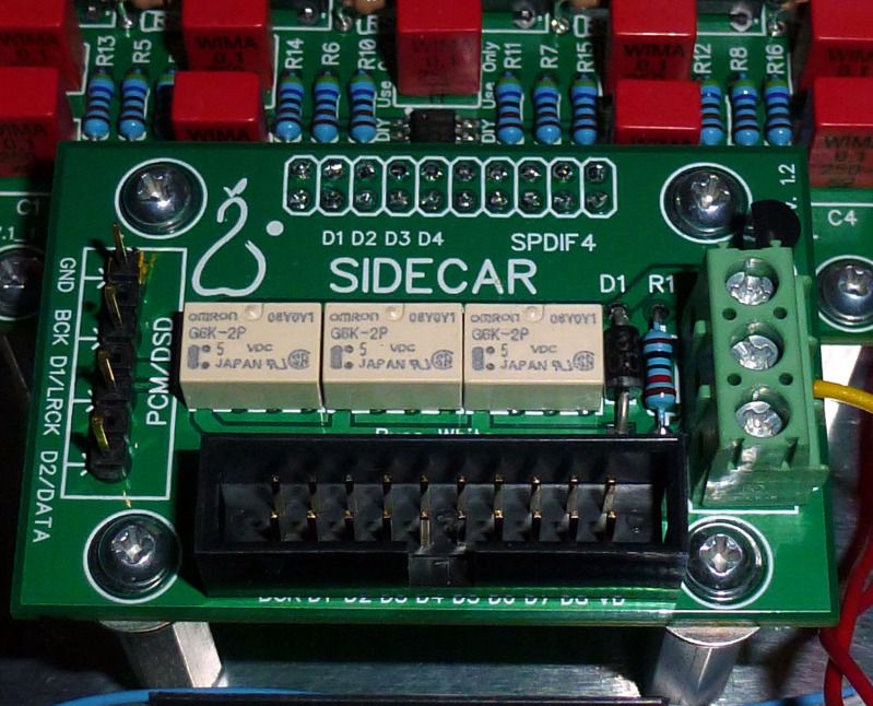 Edited by user Sunday, March 11, 2012 2:48:50 PM(UTC)
| Reason: Not specified |
|
|
|
|
|
|
Rank: Administration
Groups: Administration, Customer
Joined: 10/24/2006(UTC)
Posts: 2,869
Location: Massachusetts, USA
Thanks: 2 times
Was thanked: 141 time(s) in 134 post(s)
|
When using the Sidecar this way (triggered off the switch board) you need to drop the value of R1 on the Sidecar to something like 1K.
|
|
|
|
|
|
Rank: Member
Groups: Member
Joined: 1/6/2012(UTC)
Posts: 305
Location: Plainfield, IL
Thanks: 11 times
Was thanked: 26 time(s) in 21 post(s)
|
I either missed that resistor change detail or it isn't mentioned in the manual. Thanks. |
|
|
|
|
|
|
Rank: Administration
Groups: Administration, Customer
Joined: 10/24/2006(UTC)
Posts: 2,869
Location: Massachusetts, USA
Thanks: 2 times
Was thanked: 141 time(s) in 134 post(s)
|
It's in another thread somewhere. We didn't actually design them to work together that way, but they do. I may alter the kits to make it easier, as it seems like a good idea.
|
|
|
|
|
|
Rank: Member
Groups: Member
Joined: 1/6/2012(UTC)
Posts: 305
Location: Plainfield, IL
Thanks: 11 times
Was thanked: 26 time(s) in 21 post(s)
|
I got nothing with a forum search for 'sidecar' but got this thread with a google search. I just did what was suggested on page 16 of the Rev 1.2.2. B III Integration guide. quote] Tip: If you don’t use all 4 inputs of the S/PDIF-4 Input Board, you could just use the standard 4 position switch, and use one of the positions to switch the Sidecar module. One could do this by connecting the B (Base) terminal on the Sidecare module to the corresponding off-board LED position (on switch module: LEDs, 5). It is even possible to leave the on-board LED in place if desired. [/quote No mention of a resistor swap and I just installed what was included in the kit. It drove me crazy at first with it not working, but now I know, life is better. I'm not as savvy as most of you are, something goes wrong I think I caused it. I am learning a lot though. Edited by user Monday, March 12, 2012 12:49:04 PM(UTC)
| Reason: Not specified |
|
|
|
|
|
|
Rank: Member
Groups: Member
Joined: 12/6/2009(UTC)
Posts: 323
Location: Catalonia new Europe state
Thanks: 4 times
Was thanked: 1 time(s) in 1 post(s)
|
SCompRacer wrote:I got nothing with a forum search for 'sidecar' but got this thread with a google search. I just did what was suggested on page 16 of the Rev 1.2.2. B III Integration guide.
quote] Tip: If you don’t use all 4 inputs of the S/PDIF-4 Input Board, you could just use the standard 4 position
switch, and use one of the positions to switch the Sidecar module. One could do this by connecting the B
(Base) terminal on the Sidecare module to the corresponding off-board LED position (on switch module:
LEDs, 5). It is even possible to leave the on-board LED in place if desired. [/quote
No mention of a resistor swap and I just installed what was included in the kit. It drove me crazy at first with it not working, but now I know, life is better. I'm not as savvy as most of you are, something goes wrong I think I caused it. I am learning a lot though.
Where did you coonnected the B (Base) terminal on the Sidecare module, pin 4 selector switch?
|
|
|
|
|
|
Rank: Member
Groups: Member
Joined: 1/6/2012(UTC)
Posts: 305
Location: Plainfield, IL
Thanks: 11 times
Was thanked: 26 time(s) in 21 post(s)
|
felipe wrote:Where did you coonnected the B (Base) terminal on the Sidecare module, pin 4 selector switch? I installed a four pin header in the remote LED header location on the selector board (next to the numbers 4,3,2,1). Connect the B terminal of the Sidecar to one of those. I picked position # 4 for mine. You could also just solder a wire in the position you choose. I did install a 1K resistor in the R1 position on the Sidecar and it works fine, the signal goes through the relays. I can hear the relays click harder with the 1.9v output from the selector switch now. Before with the supplied 10K resistor in R1 the click was softer; the relay contacts did not close tightly enough to pass the signal through. Edited by user Thursday, April 5, 2012 1:20:13 PM(UTC)
| Reason: Not specified |
|
|
|
|
|
|
Rank: Administration
Groups: Administration, Customer
Joined: 10/24/2006(UTC)
Posts: 2,869
Location: Massachusetts, USA
Thanks: 2 times
Was thanked: 141 time(s) in 134 post(s)
|
SCompRacer wrote: I picked position # 4 for mine. You could also just solder a wire in the position you choose. As evidenced in this thread, it is probable best to use position #1 (or 3) if you are going to try this mod. It will, of course, only be an issue with very high resolution content on the I2S/DSD lines.
|
|
|
|
|
|
Rank: Member
Groups: Member
Joined: 1/6/2012(UTC)
Posts: 305
Location: Plainfield, IL
Thanks: 11 times
Was thanked: 26 time(s) in 21 post(s)
|
? Confused. Any of the four LED postions still outputs 1.9v though and would trip the relays in the Sidecar, correct? Provided R1 in the Sidecar was changed to the lower value of course. Edited by user Thursday, April 5, 2012 1:27:51 PM(UTC)
| Reason: Not specified |
|
|
|
|
|
|
Rank: Administration
Groups: Administration, Customer
Joined: 10/24/2006(UTC)
Posts: 3,979
Location: Nashville, TN
Thanks: 25 times
Was thanked: 89 time(s) in 83 post(s)
|
The ES9018 has an autodetect for SPDIF - if you don't turn it off it can sometimes think that PCM(I2S) is SPDIF and will unlock and try to re-lock onto what it thinks is SPDIF. By using position 1 or 3 you set the ES9018 to channel that is not very likely to have a signal that is like SPDIF. So you will get a solid lock. Position 2 & 4 are the worst to use as it is a data line for I2S, and at high sample rates the ES9018 can think it might be SPDIF and will unsuccessfully attempt to lock onto it. A better solution is to use a two pole two position switch. With one pole to GND and one to 5V. Connect the switch so that one pole goes to "B" on the sidecar, and one to I/O port B5(SPDIF auto-detect bypass) on the Buf III. The way when the switch is in one position the "B" pole will be high, and the B5 pole will be open (low). When the switch is in the other the "B" pole will be low and the B5 pin will be open (high). Now you have all 4 SPDIF selections to use and even better - I2S will "never" confuse the ES9018 as being SPDIF. Edited by user Thursday, April 5, 2012 3:14:12 PM(UTC)
| Reason: Not specified
|
|
|
|
|
|
Rank: Administration
Groups: Administration, Customer
Joined: 10/24/2006(UTC)
Posts: 3,979
Location: Nashville, TN
Thanks: 25 times
Was thanked: 89 time(s) in 83 post(s)
|
|
|
|
|
|
|
Rank: Member
Groups: Member
Joined: 1/6/2012(UTC)
Posts: 305
Location: Plainfield, IL
Thanks: 11 times
Was thanked: 26 time(s) in 21 post(s)
|
10-4, got it, understand it, thanks. ;) Kind of like this..... Edited by user Friday, April 6, 2012 6:02:04 PM(UTC)
| Reason: Not specified SCompRacer attached the following image(s): thefix.jpg (16kb) downloaded 142 time(s).You cannot view/download attachments. Try to login or register. |
|
|
|
|
|
|
Forum Jump
You cannot post new topics in this forum.
You cannot reply to topics in this forum.
You cannot delete your posts in this forum.
You cannot edit your posts in this forum.
You cannot create polls in this forum.
You cannot vote in polls in this forum.

