Rank: Member
Groups: Member
Joined: 8/17/2010(UTC)
Posts: 368
Location: australia
Thanks: 8 times
Was thanked: 3 time(s) in 3 post(s)
|
From memory the pot is on the edge of drawing too much power & the motor can cause issues with the circuit, at least that's what I have read.
|
|
|
|
|
|
Rank: Member
Groups: Member
Joined: 8/17/2010(UTC)
Posts: 368
Location: australia
Thanks: 8 times
Was thanked: 3 time(s) in 3 post(s)
|
The system has been playing quite successfully for a while now so it's time to think about getting it all into a case. At the moment I am just looking at the layout & thought you guys may have some comments on the way things are laid out. What I haven't done at this stage is make any allowance for a USB connection to play music from, I may need some advice on that. A lot of the components where already drawn by gwikse which made life a lot easier, thanks gwikse. One of the pots is for volume & the other is for a balance control, but as yet I haven't worked out how to implement the balance control so it may get flicked in the end. It has turned out impossible to get the touch screen working, there is a conflict in the software somewhere which even Henning Karlsen couldn't resolve, so for now the Apple remote will do just fine. There are a lot of people who have helped me get this far & I thank them all again. Anyway if you have some layout comments please send them through. 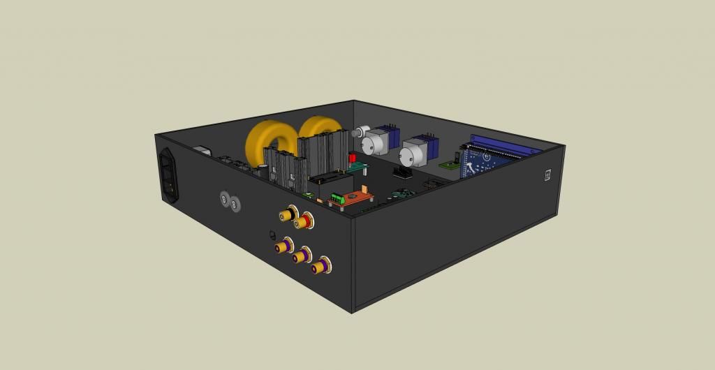 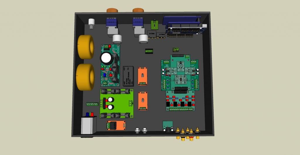 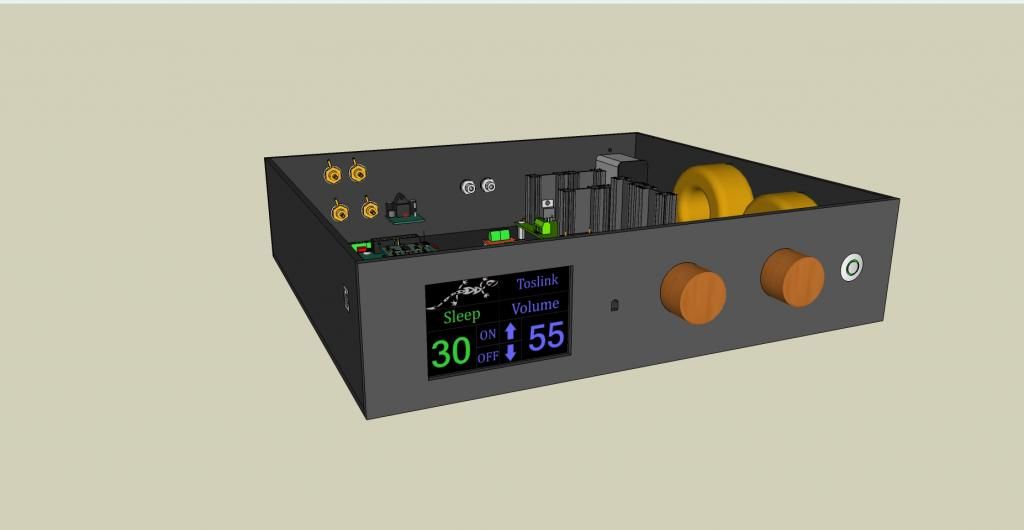
|
|
|
|
|
|
Rank: Member
Groups: Member
Joined: 1/19/2011(UTC)
Posts: 332
Location: Oslo, Norway
Thanks: 14 times
Was thanked: 17 time(s) in 17 post(s)
|
Looks great imo. Too bad about the touch screen. Perhaps you`ll get an "aha" moment regarding that later on (fingers crossed). Regarding layout: 1. Rotate the Placid HD so that the connectors are heading from the trannies (AC in) to the TPA modules (DC out). 2. Perhaps it should all be inverted (left to right). That would give a shorter distance between the Placid HD and the Buffalo). 3. I would recommend using Neutric D style holes and connectors (if you want nicer RCA connectors they will fit in the hole of the neutrik D style casing). That way Balanced/unbalanced becomes irrelevant regarding the case ;) 4. And looking at the hifiduino site lately and talking a bit with Corpius abou it, you could add a lot more inputs, so that could possibly be an idea to add holes in the back panel to allow for it later on. Again, the neutrik D style chassis connectors, can be covered with a cover plate that they make (not as expensive as making a new rear panel if you need more inputs). Happy to see that the models come in handy :) Edit: are you sure you want the arduino`s USB connection that way? I have not been updating my first controller due to something simular (makes it a lot harder to work with the coding). This would however not be an issue if you flipped left and right as previously suggested. Edited by user Friday, November 23, 2012 1:04:56 PM(UTC)
| Reason: Not specified
|
|
|
|
|
|
Rank: Member
Groups: Member
Joined: 2/1/2012(UTC)
Posts: 332
Location: The Netherlands
Thanks: 4 times
Was thanked: 18 time(s) in 18 post(s)
|
I should definitely move the placids closer towards to DAC an IV stage. You should mount an usb feedthrough at the rear panel and connect the Arduino to this on the inside. This allows you to update the software without the need to open the case. Also add another USB connector/feedthrough for any USB to I2S device. I don't see how you want some balance control with a stereo pot. Yes, you have two channels, but when turning the pot the volume of both channels raises or gets dimmed at the same time. You could use two separate pots for this. There is however a much more elegant solution. You can use a digital potentiometer that is controlled by the arduino. I'm using such an pot in my project for dimming the lcd backlight. I use a MCP42010 for this. It has two channels that can both be set independently from each other. I can help you with the code if you decide to use such an pot. A while ago I posted some code examples on my website on how to use this pot. http://www.ce-designs.ne...control-it-using-arduino |
|
|
|
|
|
|
Rank: Member
Groups: Member
Joined: 8/17/2010(UTC)
Posts: 368
Location: australia
Thanks: 8 times
Was thanked: 3 time(s) in 3 post(s)
|
Thanks for the input, I'll ponder your thoughts, and respond later tonight when I get back home, I thought I'd clear up one thing while I had 5 minutes, my picture wasn't clear but as you will see the USB input can be accessed from the side panel. 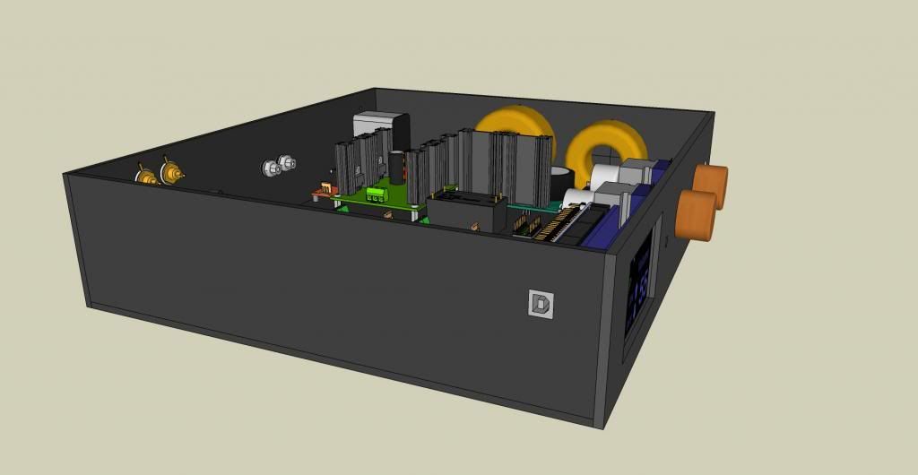
|
|
|
|
|
|
Rank: Member
Groups: Member
Joined: 8/17/2010(UTC)
Posts: 368
Location: australia
Thanks: 8 times
Was thanked: 3 time(s) in 3 post(s)
|
Originally Posted by: gwikse  Looks great imo. Too bad about the touch screen. Perhaps you`ll get an "aha" moment regarding that later on (fingers crossed).
Regarding layout:
1. Rotate the Placid HD so that the connectors are heading from the trannies (AC in) to the TPA modules (DC out).
2. Perhaps it should all be inverted (left to right). That would give a shorter distance between the Placid HD and the Buffalo).
3. I would recommend using Neutric D style holes and connectors (if you want nicer RCA connectors they will fit in the hole of the neutrik D style casing). That way Balanced/unbalanced becomes irrelevant regarding the case ;)
4. And looking at the hifiduino site lately and talking a bit with Corpius abou it, you could add a lot more inputs, so that could possibly be an idea to add holes in the back panel to allow for it later on. Again, the neutrik D style chassis connectors, can be covered with a cover plate that they make (not as expensive as making a new rear panel if you need more inputs).
Happy to see that the models come in handy :)
Edit: are you sure you want the arduino`s USB connection that way? I have not been updating my first controller due to something simular (makes it a lot harder to work with the coding). This would however not be an issue if you flipped left and right as previously suggested. 1: I rotated the HD the way I think you mean. 2: I had the whole thing inverted originally but wanted side (close to front) access to the Mega USB so I would have easy access to the for when it goes in the cabinet, I haven't built yet :) 3: I will go with the Neutric D as suggested. 4: What would I do with a lot more inputs, at this stage I only have the 4 way input board. 5: What hardware would I need to add to get a USB in? 6: Is there a way to get an IPOD Input ? do IPODS have digital outputs? Edited by user Saturday, November 24, 2012 10:35:04 AM(UTC)
| Reason: Not specified
|
|
|
|
|
|
Rank: Member
Groups: Member
Joined: 8/17/2010(UTC)
Posts: 368
Location: australia
Thanks: 8 times
Was thanked: 3 time(s) in 3 post(s)
|
Originally Posted by: Corpius I should definitely move the placids closer towards to DAC an IV stage. You should mount an usb feedthrough at the rear panel and connect the Arduino to this on the inside. This allows you to update the software without the need to open the case. Also add another USB connector/feedthrough for any USB to I2S device. I don't see how you want some balance control with a stereo pot. Yes, you have two channels, but when turning the pot the volume of both channels raises or gets dimmed at the same time. You could use two separate pots for this. There is however a much more elegant solution. You can use a digital potentiometer that is controlled by the arduino. I'm using such an pot in my project for dimming the lcd backlight. I use a MCP42010 for this. It has two channels that can both be set independently from each other. I can help you with the code if you decide to use such an pot. A while ago I posted some code examples on my website on how to use this pot. http://www.ce-designs.ne...control-it-using-arduino 1: Why would you move the Placid's closer, I was trying to keep the power section away from the Dac/Control section. 2: I will probably add the extra USB as suggested. 3: The Balance control can be implemented like this: I was probably going to try the setup shown in Figure 5 http://sound.westhost.com/project01.htm but leaving out he volume pot. 4: I would definitely prefer to use the digital approach but couldn't work out how to implement it.
|
|
|
|
|
|
Rank: Member
Groups: Member
Joined: 1/19/2011(UTC)
Posts: 332
Location: Oslo, Norway
Thanks: 14 times
Was thanked: 17 time(s) in 17 post(s)
|
Hello. I tried to make a visible model of the routing of signals etc to get: 4 Consumer lvl or AES/EBU sp-dif 4 Optical inputs (TTL level) 1 USB input (via sidecar) The inputs are controlled by your arduino and if you look at the coloring you will see wich input goes where (not yet drawn in the usb / i2s source). Beware though, that the code atm supports up to 6 inputs. You would need: 1 Sidecar (if you do not allready have it) 1 USB input card (Amanero, WaweIO, exa, etc) 4 additional TTL level sp-dif input solutions. TPA`s Optical module, single sp-dif input card for the B3 etc. Edit: Eeeeh never mind, this would not work as you would then have live TTL sources connected to D5-D8 even when the sidecar is switched to the i2s source. Edited by user Saturday, November 24, 2012 11:24:29 AM(UTC)
| Reason: Not specified gwikse attached the following image(s):  custom inputs.jpg (172kb) downloaded 28 time(s).You cannot view/download attachments. Try to login or register.
|
|
|
|
|
|
Forum Jump
You cannot post new topics in this forum.
You cannot reply to topics in this forum.
You cannot delete your posts in this forum.
You cannot edit your posts in this forum.
You cannot create polls in this forum.
You cannot vote in polls in this forum.

