Rank: Member
Groups: Member
Joined: 1/19/2011(UTC)
Posts: 332
Location: Oslo, Norway
Thanks: 14 times
Was thanked: 17 time(s) in 17 post(s)
|
I am working on a system. Here is a 3d model of it. To start off there will be: 2 B3`s with sidecar and sp-dif switch 1 BNC, 1 RCA and 1 Optical 1 Exau2s (4th pos on the switch module selects the external i2s source on the sidecar) 2 Legato 3.1`s with buffers 2 Placid HD BP (with taller heatsinks) 2 LCDPS (one to power control systems etc, the other to the dac`s) Later on a couple Ventus might find its way into the case so I want the case to be designed with that in mind (2x ventus boards and additional Placid`s). Hifiduino based control and lcd (not during first tests though). I have kept the wires as short and kept as far from each other as possible by mounting the modules horisontally. Power at the bottom and i2s and signal at the top of the case. Here is the preliminary model. It will be a work in progress for quite some time and suggestions are welcome. Thanks in advance :)  
|
|
|
|
|
|
Rank: Administration
Groups: Administration, Customer
Joined: 10/24/2006(UTC)
Posts: 3,979
Location: Nashville, TN
Thanks: 25 times
Was thanked: 89 time(s) in 83 post(s)
|
I have to say it looks like well thought out concept. I have not had time to look too closely, but my initial take is that it should be very very good.
|
|
|
|
|
|
Rank: Member
Groups: Member
Joined: 1/19/2011(UTC)
Posts: 332
Location: Oslo, Norway
Thanks: 14 times
Was thanked: 17 time(s) in 17 post(s)
|
Thank you for the feedback. I am for the time being looking at other control options. I would have preferred it all to be Twisted Pear so if the AC2 is nearing it`s completion or at least at the near end of the test phase then I`ll use that. I think I read it in a thread at diyaudio that you are done with the hardware part of the ac2. So I`ll hold off on the arduino based control part untill I see what you come up with. As for the dac itself there are a few things I am thinking of atm. 1. Are the boards in my model too close together (noice issues)? 2. Can I mount the tridents that close to the board with only about 5mm clearence or will this cause issues? Digital and analog part: http://sketchup.google.c...80d810a177a6ddd614bc0906Power and control: http://sketchup.google.c...7bb5a4fb77a6ddd614bc0906Edit: updated the model Edited by user Saturday, March 10, 2012 4:36:15 PM(UTC)
| Reason: Not specified
|
|
|
|
|
|
Rank: Member
Groups: Member
Joined: 1/19/2011(UTC)
Posts: 332
Location: Oslo, Norway
Thanks: 14 times
Was thanked: 17 time(s) in 17 post(s)
|
Started putting it together. I seem to have forgotten to order 12mm Metric distances. So that needs to be ordered. Was planning on using the Tridents that was bought a while ago, I think they are V1, but so far it is open. Should I use the updated V3? gwikse attached the following image(s):  DM B3.jpg (237kb) downloaded 153 time(s).You cannot view/download attachments. Try to login or register.
|
|
|
|
|
|
Rank: Member
Groups: Member
Joined: 1/19/2011(UTC)
Posts: 332
Location: Oslo, Norway
Thanks: 14 times
Was thanked: 17 time(s) in 17 post(s)
|
Some testing. I have put one half of the dac`s together. This will eventuelly be the right channel. So far I have tested it with TTL level optical input and it lock on signals ranging from 16bit 44.1 up to 24bit 96 just as expected. All dip switches are set to off atm. The heatsink closest to the camera is hot as .... too hot to hold for any lenght of time, but not hot enough to leave a mark (note that my fingers are hardened from playing guitar as well as from testing blood sugar for the last 30 years). Will place a temperature probe on it later on, when I can place it closer to my computer (with it`s temp probes that can be logged). gwikse attached the following image(s): Placid HD out stable.jpg (207kb) downloaded 98 time(s). Placid Sourced.jpg (196kb) downloaded 82 time(s). Placid shunted.jpg (173kb) downloaded 79 time(s). transformer loaded.jpg (207kb) downloaded 66 time(s). transformer unloaded.jpg (216kb) downloaded 98 time(s).You cannot view/download attachments. Try to login or register.
|
|
|
|
|
|
Rank: Administration
Groups: Administration, Customer
Joined: 10/24/2006(UTC)
Posts: 3,979
Location: Nashville, TN
Thanks: 25 times
Was thanked: 89 time(s) in 83 post(s)
|
Which that PS running at 510ma with no load it is going to run very very hot. It will cool down a bit when the load is dissipating more of the energy.
|
|
|
|
|
|
Rank: Administration
Groups: Administration, Customer
Joined: 10/24/2006(UTC)
Posts: 3,979
Location: Nashville, TN
Thanks: 25 times
Was thanked: 89 time(s) in 83 post(s)
|
V3 Tridents are better than V1.1 in many ways.
|
|
|
|
|
|
Rank: Member
Groups: Member
Joined: 1/19/2011(UTC)
Posts: 332
Location: Oslo, Norway
Thanks: 14 times
Was thanked: 17 time(s) in 17 post(s)
|
Yes I am aware that the placids running without load at these levels would make them extremely hot. However, atm it is only shunting ~75mA. The rest (of the 520mA sourced) is powering the B3 and optical module. Am I to understand that even though they are connected, and from what I can see "using" the sourced current, the placid will run far less hot when playing music? The drop in voltage is from ~5.2V to ~5.1V I have already fitted trident V1.1 (AVCC and tridents are underneath the pcb). The Placid HDBP was also connected tonight, and is now ready for the ivy stage. Will do a test of LCDPS/LCBPS vs Placid later on. Still waiting for parts for the arduino control and some connectors in order to do a proper AB test between the two. gwikse attached the following image(s): Ready for Ivy3.jpg (194kb) downloaded 86 time(s).You cannot view/download attachments. Try to login or register.
|
|
|
|
|
|
Rank: Administration
Groups: Administration, Customer
Joined: 10/24/2006(UTC)
Posts: 2,869
Location: Massachusetts, USA
Thanks: 2 times
Was thanked: 141 time(s) in 134 post(s)
|
The Placid heatsinks run hot. It's fine. Expect to see up to a 50-60C heatsink in operation. That's a typical idle temp for a Class-A amp, so it's not crazy (it is atypical in digital circuits).
50C is usually estimated as 2-3 seconds touch to the heatsink before you need to pull away (though we actually measure with a IR probe in testing :) ).
|
|
|
|
|
|
Rank: Member
Groups: Member
Joined: 1/19/2011(UTC)
Posts: 332
Location: Oslo, Norway
Thanks: 14 times
Was thanked: 17 time(s) in 17 post(s)
|
I think it will be fine. It can be made to run a little less hot though. I will cut some holes in the bottom along the red lines. That way the heat will rise and "fresh" cold air will be drawn in through the holes. But enough about heat for now. I am a little curious to how the power supply`s handle high AC main voltages. I have measured the AC here and it is around 240VAC. The highest I have seen using a power-logger is 245VAC. The lowest I have measured was 235VAC. Most transformers I have used have given fairly high voltages compared to what they are supposed to be. My 15V transformers give about 17VAC and my 9V`s give around 10,5VAC. This would cause the power supply`s to run hotter correct? Are there any other disadvantages of high AC lines? Best Gunnar gwikse attached the following image(s): Vent holes.jpg (189kb) downloaded 59 time(s). vent holes 2.jpg (183kb) downloaded 52 time(s). side by side test 1.jpg (146kb) downloaded 69 time(s). front.jpg (155kb) downloaded 64 time(s). stacked.jpg (157kb) downloaded 87 time(s).You cannot view/download attachments. Try to login or register.
|
|
|
|
|
|
Rank: Member
Groups: Member
Joined: 8/17/2010(UTC)
Posts: 368
Location: australia
Thanks: 8 times
Was thanked: 3 time(s) in 3 post(s)
|
My AC regularly sits at 252v, I always wondered if this was an issue.
|
|
|
|
|
|
Rank: Administration
Groups: Administration, Customer
Joined: 10/24/2006(UTC)
Posts: 3,979
Location: Nashville, TN
Thanks: 25 times
Was thanked: 89 time(s) in 83 post(s)
|
Well you definitely could go a bit lower on the secondary voltage or larger on the heatsinks, but you should still be ok.
|
|
|
|
|
|
Rank: Member
Groups: Member
Joined: 1/19/2011(UTC)
Posts: 332
Location: Oslo, Norway
Thanks: 14 times
Was thanked: 17 time(s) in 17 post(s)
|
Power supply section more or less up and running (still need to fit the AC in properly). The transformers are underneath the plate that the placids are mounted on. The "sinks" are bent 4MM alu that is perfectly aligned to transfer the heat to the top lid. Everything is powder coated jet black. mms_20151104_063542.jpg (82kb) downloaded 57 time(s).Edited by user Wednesday, December 23, 2015 9:14:37 AM(UTC)
| Reason: Not specified
|
|
|
|
|
|
Rank: Member
Groups: Member
Joined: 9/23/2015(UTC) Posts: 89  Thanks: 5 times
|
Looks nice!
Im really interested in hearing how the heat transfer to the top lid performs.
|
|
|
|
|
|
Rank: Member
Groups: Member
Joined: 1/19/2011(UTC)
Posts: 332
Location: Oslo, Norway
Thanks: 14 times
Was thanked: 17 time(s) in 17 post(s)
|
Thanks,
With the top lid on the entire case becomes a heat sink (since everything is powder coated and transfer heat well). But I need to cut some more holes in it as there are currently no holes above the PSU section. I will add a fan on the left rear of the case to draw some air out when the case temp reach 40c or so.
Got rid of some hum from the transformers by adding a soft start from hypex. I have to route the AC wires properly, I hope I get the time to get it done in the next few days.
|
|
|
|
|
|
Rank: Member
Groups: Member
Joined: 1/19/2011(UTC)
Posts: 332
Location: Oslo, Norway
Thanks: 14 times
Was thanked: 17 time(s) in 17 post(s)
|
Test fitting the DAC boards above the iv stage. I have room to install a newclassd opamp there as well. DSC_0139.JPG (312kb) downloaded 19 time(s). testfitIV+.jpg (118kb) downloaded 23 time(s).Edited by user Wednesday, December 23, 2015 9:18:56 AM(UTC)
| Reason: Not specified
|
|
|
|
|
|
Rank: Member
Groups: Member
Joined: 1/6/2012(UTC)
Posts: 305
Location: Plainfield, IL
Thanks: 11 times
Was thanked: 26 time(s) in 21 post(s)
|
Nice work gwikse! Four years now and my dual mono BIII resides in the rack. Some folks have brought DAC's over to knock it off but haven't succeeded.
|
|
|
|
|
|
|
Rank: Member
Groups: Member
Joined: 1/19/2011(UTC)
Posts: 332
Location: Oslo, Norway
Thanks: 14 times
Was thanked: 17 time(s) in 17 post(s)
|
Thanks. Happy to hear that you are happy with the sound of your DAC as it in many ways is simular to this build. Atm I am working on getting the computer side of things up and running. The computer parts are not desided yet, but I was thinking of using a raspberry pi solution for added connectivity with airplay etc. Now I am a little curious of the Hermes/chronos BBB solution. We will be using a Streacom FC5 chassis to house the PC and the streaming solution and its power supplies (regs mounted to the left heatsink). fc5b_alpha_090000.jpg (147kb) downloaded 26 time(s).
|
|
|
|
|
|
Rank: Member
Groups: Member
Joined: 1/6/2012(UTC)
Posts: 305
Location: Plainfield, IL
Thanks: 11 times
Was thanked: 26 time(s) in 21 post(s)
|
Nice start! I was about to build a music server when a great deal popped up on a used one. A fanless Signature Series Sonore with Deux power supply music server. Intel dh77df motherboard, i5 2.7GHz cpu, 8GB Corsair xms3 DDR3 ram. 3TB WD Green. Hard drive isolation, SoTM USB card, SoTM sata power filter, two custom power supplies for PC/USB card. I upgraded it with an 80GB msata SSD boot drive that I closed (no storage) and increased from 3TB to a 6TB drive giving me some space to grow into. Had Vortexbox 2.2, I used the new version 2.4 with 64bit Fedora 23. 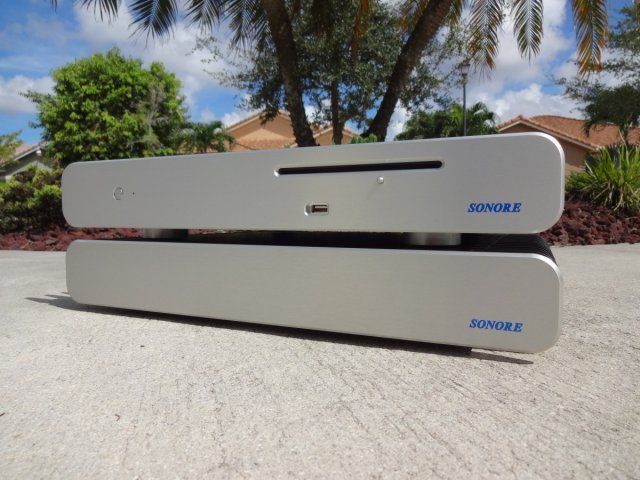 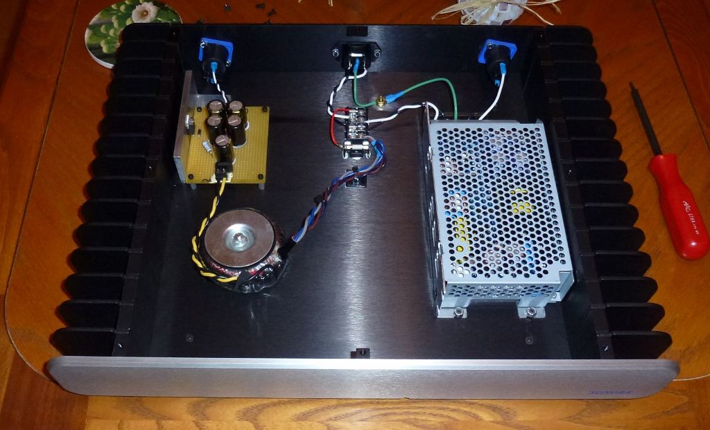 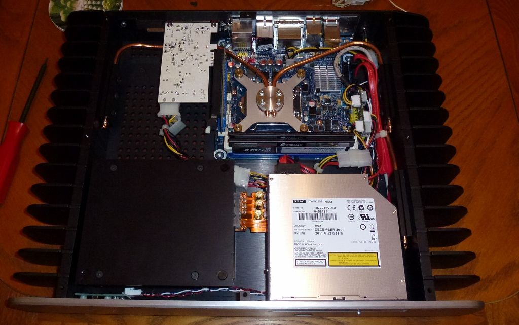 |
|
|
|
|
|
|
Rank: Administration
Groups: Administration, Customer
Joined: 10/24/2006(UTC)
Posts: 3,979
Location: Nashville, TN
Thanks: 25 times
Was thanked: 89 time(s) in 83 post(s)
|
|
|
|
|
|
|
Forum Jump
You cannot post new topics in this forum.
You cannot reply to topics in this forum.
You cannot delete your posts in this forum.
You cannot edit your posts in this forum.
You cannot create polls in this forum.
You cannot vote in polls in this forum.

